Brake Booster -- Installation |
| 1. TEMPORARILY TIGHTEN BRAKE MASTER CYLINDER PUSH ROD CLEVIS |
Install the lock nut and brake master cylinder push rod clevis to the brake booster assembly.
- HINT:
- Fully tighten the lock nut after adjusting the brake pedal height.
| 2. INSTALL BRAKE BOOSTER GASKET |
Install a new brake booster gasket to the brake booster assembly.
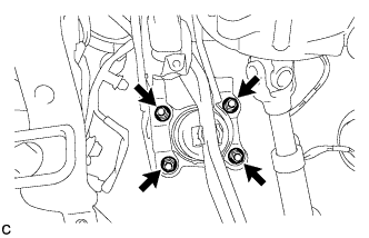
| 3. INSTALL BRAKE BOOSTER ASSEMBLY |
Install the brake booster assembly to the body with the 4 nuts.
- Torque:
- 13 N*m{132 kgf*cm, 10 ft.*lbf}
- NOTICE:
- Do not damage the brake lines or fuel lines.
 |
Engage the 2 clamps to install the brake lines to the body.
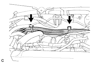 |
| 4. INSTALL NO. 5 FRONT BRAKE TUBE |
Install the No. 5 front brake tube to the body and engage the grommet.
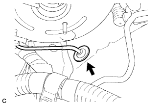 |
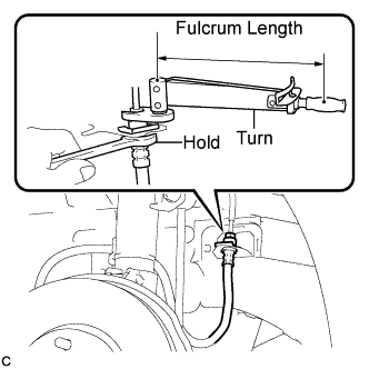
Using a union nut wrench (10 mm), connect the No. 5 front brake tube to the front brake flexible hose LH.
- Torque:
- without a union nut wrench:
- 15 N*m{155 kgf*cm, 11 ft.*lbf}
- with a union nut wrench:
- 14 N*m{143 kgf*cm, 10 ft.*lbf}
- NOTICE:
- Use a torque wrench with a fulcrum length of 250 mm (9.84 in.).
- This torque value is effective when the union nut wrench is parallel to the torque wrench.
 |
| 5. INSTALL CHECK VALVE GROMMET |
Install a new check valve grommet to the brake booster assembly.
| 6. INSTALL BRAKE VACUUM CHECK VALVE ASSEMBLY |
Install the vacuum check valve assembly to the brake booster assembly.
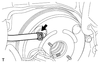
| 7. CONNECT VACUUM HOSE |
Connect the vacuum hose and slide the clip.
 |
| 8. CONNECT BRAKE MASTER CYLINDER PUSH ROD CLEVIS |
Apply lithium soap base glycol grease to the push rod pin.
 |
Connect the brake master cylinder push rod clevis to the brake pedal with the push rod clevis pin, and install a new clip as shown in the illustration.
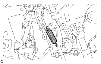
| 9. INSTALL BRAKE PEDAL RETURN SPRING |
Install the brake pedal return spring between the brake pedal support sub-assembly and brake master cylinder push rod clevis.
 |
| 10. INSTALL FRONT WHEEL LH |
- Torque:
- 103 N*m{1050 kgf*cm, 76 ft.*lbf}
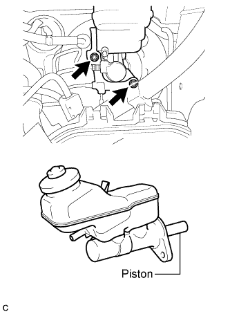
| 11. INSTALL BRAKE MASTER CYLINDER SUB-ASSEMBLY |
Install a new O-ring to the brake master cylinder sub-assembly.
Install the brake master cylinder sub-assembly and brake tube way to the brake booster assembly with the 2 nuts.
- Torque:
- 13 N*m{132 kgf*cm, 10 ft.*lbf}
- NOTICE:
- The master cylinder requires careful handling. Do not allow the master cylinder to receive any impact, such as from being dropped. Do not reuse a master cylinder that has been dropped.
- Do not strike or pinch the master cylinder piston, and do not cause any damage to the master cylinder piston by any other means.
- When installing the master cylinder to the brake booster, or when removing the master cylinder from the brake booster, make sure that the master cylinder is kept horizontal or its tip faces downward (the piston faces upward) to prevent the master cylinder piston from falling off.
- Do not allow any foreign objects to contaminate the master cylinder piston. If a foreign object gets on the piston, remove it by using a piece of cloth and then apply an even layer of lithium soap base glycol grease around the circumference (sliding part) of the piston.
- Do not use any other type of grease or fluid.
 |
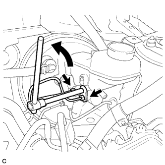
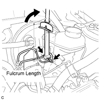
Using a union nut wrench (10 mm or 12 mm), connect the 4 brake lines to the brake master cylinder sub-assembly.
- Torque:
- w/o VSC without a union nut wrench:
- 15 N*m{155 kgf*cm, 11 ft.*lbf}
- w/o VSC with a union nut wrench:
- 14 N*m{143 kgf*cm, 10 ft.*lbf}
- w/ VSC without a union nut wrench:
- 20 N*m{200 kgf*cm, 14 ft.*lbf}
- w/ VSC with a union nut wrench:
- 18 N*m{178 kgf*cm, 13 ft.*lbf}
- NOTICE:
- Use a torque wrench with a fulcrum length of 250 mm (9.84 in.).
- This torque value is effective when the union nut wrench is parallel to the torque wrench.
 |
Engage the clamp and connect the connector.
 |
| 12. CONNECT CLUTCH TUBE (for Manual Transaxle) |
Connect the clutch tube to the brake master cylinder reservoir assembly with the clip.
 |
| 13. FILL RESERVOIR WITH BRAKE FLUID |
Fill the reservoir with brake fluid.
- Brake Fluid:
- SAE J1703 or FMVSS No. 116 DOT 3
- NOTICE:
- Add brake fluid to keep the level between the MIN and MAX lines of the reservoir while bleeding the brakes.
| 14. BLEED CLUTCH LINE |
| 15. BLEED BRAKE MASTER CYLINDER |
- NOTICE:
- If the master cylinder is reinstalled or if the reservoir becomes empty, bleed the master cylinder.
- To prevent brake fluid from damaging painted surface, cover any surrounding parts with a piece of cloth.
Using a union nut wrench (10 mm or 12 mm), disconnect the 2 brake lines from the master cylinder.
 |
Slowly depress the brake pedal and hold it*1.
 |
Cover the 2 outer holes with fingers, and release the brake pedal*2.
 |
Repeat *1 and *2 3 or 4 times.
Using a union nut wrench (10 mm or 12 mm), connect the 2 brake lines to the master cylinder.
- Torque:
- w/o VSC without a union nut wrench:
- 15 N*m{155 kgf*cm, 11 ft.*lbf}
- w/o VSC with a union nut wrench:
- 14 N*m{143 kgf*cm, 10 ft.*lbf}
- w/ VSC without a union nut wrench:
- 20 N*m{200 kgf*cm, 14 ft.*lbf}
- w/ VSC with a union nut wrench:
- 18 N*m{178 kgf*cm, 13 ft.*lbf}
- NOTICE:
- Use a torque wrench with a fulcrum length of 250 mm (9.84 in.).
- This torque value is effective when the union nut wrench is parallel to the torque wrench.
 |
| 16. BLEED BRAKE LINE |
- NOTICE:
- Bleed the brake line of the wheel farthest from the master cylinder first.
- Add brake fluid to keep the level between the MIN and MAX lines of the reservoir while bleeding the brakes.
Connect a vinyl tube to the bleeder plug.
Depress the brake pedal several times, and then loosen the bleeder plug with the pedal depressed*1.
When fluid stops coming out, tighten the bleeder plug, and then release the brake pedal*2.
Repeat *1 and *2 until all the air in the fluid is completely bled out.
Tighten the bleeder plug completely.
- Torque:
- Front bleeder plug:
- 8.3 N*m{85 kgf*cm, 73 in.*lbf}
- Rear bleeder plug (for Drum Brake):
- 8.5 N*m{87 kgf*cm, 75 in.*lbf}
- Rear bleeder plug (for Disc Brake):
- 10 N*m{102 kgf*cm, 7 ft.*lbf}
Repeat the above procedure for each wheel to bleed the brake line.
| 17. BLEED BRAKE ACTUATOR (w/ VSC) |
- NOTICE:
- After bleeding the brake system, if the specified height or feel of the brake pedal cannot be obtained, bleed the brake actuator assembly with the Techstream by following the procedure below.
Depress the brake pedal more than 20 times with the ignition switch off.
Connect the Techstream to the DLC3, and then turn the ignition switch to ON.
- NOTICE:
- Do not start the engine.
Turn the Techstream on and select "Air Bleeding" on the screen.
- NOTICE:
- Refer to the Techstream operator's manual for further details.
- Bleed air by following the steps displayed on the Techstream.
Bleed air according to "Step 1: Increase Line" on the Techstream display.
- NOTICE:
- Make sure that the master cylinder reservoir tank does not run out of brake fluid.
- Add brake fluid to keep the level between the MIN and MAX lines of the reservoir while bleeding the brakes.
Connect a vinyl tube to either one of the bleeder plugs.
Depress the brake pedal several times, and then loosen the bleeder plug connected to the vinyl tube with the pedal depressed*3.
When fluid stops coming out, tighten the bleeder plug, and then release the brake pedal*4.
Repeat *3 and *4 until all the air in the fluid is completely bled out.
Tighten the bleeder plug completely.
- Torque:
- Front bleeder plug:
- 8.3 N*m{85 kgf*cm, 73 in.*lbf}
- Rear bleeder plug (for Drum Brake):
- 8.5 N*m{87 kgf*cm, 75 in.*lbf}
- Rear bleeder plug (for Disc Brake):
- 10 N*m{102 kgf*cm, 7 ft.*lbf}
Repeat the above procedure for the rest of the wheels to bleed the brake lines.
Bleed the suction line according to "Step 2: Inhalation Line" on the Techstream display.
- NOTICE:
- Bleed the suction line by following the steps displayed on the Techstream.
- Add brake fluid to keep the level between the MIN and MAX lines of the reservoir while bleeding the brakes.
Connect a vinyl tube to the bleeder plug at the right front wheel or the right rear wheel and loosen the bleeder plug.
Operate the brake actuator assembly to bleed air using the Techstream*5.
- NOTICE:
- During this step, be sure to release the brake pedal.
- The actuator operation stops automatically in 4 seconds.
Check that the actuator operation has stopped by referring to the Techstream display, and tighten the bleeder plug*6.
Repeat *5 and *6 until all the air in the fluid is completely bled out.
Tighten the bleeder plug completely.
- Torque:
- Front bleeder plug:
- 8.3 N*m{85 kgf*cm, 73 in.*lbf}
- Rear bleeder plug (for Drum Brake):
- 8.5 N*m{87 kgf*cm, 75 in.*lbf}
- Rear bleeder plug (for Disc Brake):
- 10 N*m{102 kgf*cm, 7 ft.*lbf}
For the rest of the wheels, bleed air in the same way as stated in the above procedure.
Bleed the pressure reduction line according to "Step 3: Decrease Line" on the Techstream display.
- NOTICE:
- Bleed the pressure reduction line by following the steps displayed on the Techstream.
- Add brake fluid to keep the level between the MIN and MAX lines of the reservoir while bleeding the brakes.
Connect a vinyl tube to either one of the bleeder plugs.
Loosen the bleeder plug*7.
While keeping the brake pedal fully depressed, operate the brake actuator assembly using the Techstream.
- NOTICE:
- The actuator operation stops automatically in 4 seconds. When performing this procedure continuously, an interval of at least 20 seconds is required.
- After the operation is completed, the brake pedal goes down slightly. This is a normal phenomenon when the solenoid opens.
- During this procedure, the pedal seems heavy, but completely depress it so that the brake fluid comes out from the bleeder plug.
- Be sure to keep the brake pedal depressed. Never depress and release the pedal repeatedly.
Tighten the bleeder plug, and then release the brake pedal*8.
Repeat steps *7 to *8 until all the air in the fluid is completely bled out.
Tighten the bleeder plug completely.
- Torque:
- Front bleeder plug:
- 8.3 N*m{85 kgf*cm, 73 in.*lbf}
- Rear bleeder plug (for Drum Brake):
- 8.5 N*m{87 kgf*cm, 75 in.*lbf}
- Rear bleeder plug (for Disc Brake):
- 10 N*m{102 kgf*cm, 7 ft.*lbf}
Repeat the above procedure for the rest of the brakes to bleed the brake lines.
Bleed the brake lines again according to "Step 4: Increase Line" on the Techstream display.
- NOTICE:
- Bleed air by following the steps displayed on the Techstream.
- Add brake fluid to keep the level between the MIN and MAX lines of the reservoir while bleeding the brakes.
Connect a vinyl tube to either one of the bleeder plugs.
Depress the brake pedal several times, and then loosen the bleeder plug connected to the vinyl tube with the pedal depressed*9.
When fluid stops coming out, tighten the bleeder plug, and then release the brake pedal*10.
Repeat *9 and *10 until all the air in the fluid is completely bled out.
Tighten the bleeder plug completely.
- Torque:
- Front bleeder plug:
- 8.3 N*m{85 kgf*cm, 73 in.*lbf}
- Rear bleeder plug (for Drum Brake):
- 8.5 N*m{87 kgf*cm, 75 in.*lbf}
- Rear bleeder plug (for Disc Brake):
- 10 N*m{102 kgf*cm, 7 ft.*lbf}
Repeat the above procedure for each brake to bleed the brake lines.
Finish "Air Bleeding" on the Techstream, and then turn the Techstream off.
Disconnect the Techstream from the DLC3.
Turn the ignition switch off.
| 18. INSPECT FOR BRAKE FLUID LEAK |
| 19. INSPECT FLUID LEVEL |
Check the fluid level.
If brake fluid level is lower than the MIN line, check for leaks and inspect the disc brake pads. If necessary, refill the reservoir with brake fluid to the MAX line after repair or replacement.- Brake Fluid:
- SAE J1703 or FMVSS No. 116 DOT 3
 |
| 20. INSPECT AND ADJUST BRAKE PEDAL HEIGHT |
Check the brake pedal height.
Turn back the carpet.
Turn back the dash silencer from the slit provided on the dash silencer.
Measure the shortest distance between the brake pedal surface and dash panel.
- Pedal height from floor panel:
- 141.4 to 151.4 mm (5.57 to 5.96 in.)

Adjust the brake pedal height.
Disconnect the stop light switch connector.
Remove the stop light switch assembly.
Loosen the push rod clevis lock nut.
Adjust the brake pedal height by turning the push rod.
Tighten the push rod clevis lock nut.
- Torque:
- 26 N*m{265 kgf*cm, 19 ft.*lbf}
Insert the stop light switch into the adjuster mounting until the switch body touches the brake pedal.
- NOTICE:
- Do not depress the brake pedal.
Adjust the stop light switch (Link).
Connect the stop light switch connector.
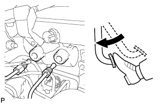
| 21. INSPECT BRAKE PEDAL FREE PLAY |
Stop the engine. Depress the brake pedal several times until no vacuum is left in the brake booster. Release the brake pedal.
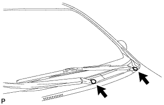
Depress the pedal until a slight resistance is felt. Measure the distance as shown in the illustration.
- Pedal free play:
- 1.0 to 6.0 mm (0.0394 to 0.236 in.)
 |
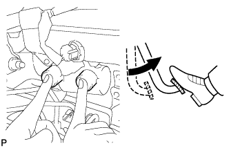
| 22. INSPECT BRAKE PEDAL RESERVE DISTANCE |
- HINT:
- Measure the distance at the same point used for the brake pedal height inspection.
Release the parking brake lever.
With the engine running, depress the brake pedal and measure the pedal reserve distance as shown in the illustration.
- Pedal Reserve Distance from the Dash Panel at 294 N (30 kgf, 66 lbf):
Specified Condition w/ ABS 81 mm (3.19 in.) w/ VSC 87 mm (3.43 in.)
 |
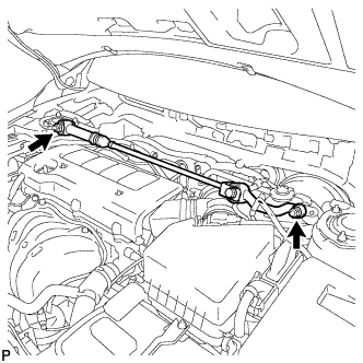
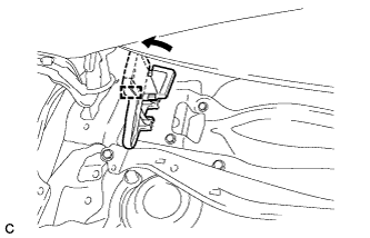
| 23. INSTALL SUSPENSION TOWER DAMPER ASSEMBLY (w/ Front Strut Bar) |
Fully tighten the 2 nuts.
- Torque:
- 52 N*m{530 kgf*cm, 38 ft.*lbf}
 |
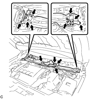
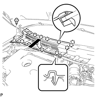
| 24. INSTALL OUTER COWL TOP PANEL (for TMC Made) |
Install the outer cowl top panel with the 12 bolts.
- Torque:
- 8.8 N*m{90 kgf*cm, 78 in.*lbf}
 |
Engage the clamp.
Bend the water guard plate RH as shown in the illustration and engage the clamp.
 |
| 25. INSTALL OUTER COWL TOP PANEL (except TMC Made) |
Install the outer cowl top panel with the 12 bolts.
- Torque:
- 8.8 N*m{90 kgf*cm, 78 in.*lbf}
 |
Engage the clamp.
Bend the water guard plate RH as shown in the illustration, and engage the clamp.
|
Bend the No. 1 heater air duct splash shield seal as shown in the illustration, and engage the clamp.
 |
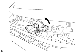
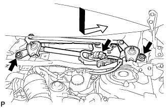
| 26. INSTALL WINDSHIELD WIPER MOTOR AND LINK ASSEMBLY |
Install the windshield wiper motor and link assembly with the 2 bolts.
- Torque:
- 5.5 N*m{56 kgf*cm, 49 in.*lbf}
 |
Connect the connector.
| 27. INSTALL COWL TOP VENTILATOR LOUVER LH |
Engage the clip and 8 claws to install the cowl top ventilator louver LH.
 |
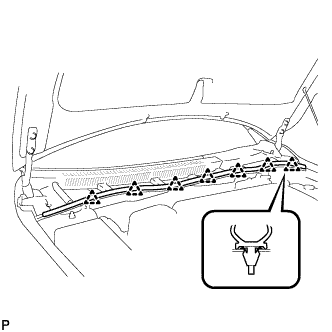
| 28. INSTALL CENTER NO. 1 COWL TOP VENTILATOR LOUVER |
Engage the clip and 14 claws to install the center No. 1 cowl top ventilator louver.
 |
| 29. INSTALL HOOD TO COWL TOP SEAL |
Engage the 7 clips to install the hood to cowl top seal.
 |
| 30. INSTALL FRONT WIPER ARM AND BLADE ASSEMBLY RH |
Operate the wiper and stop the windshield wiper motor at the automatic stop position.
Clean the wiper arm serrations.
 |
When reinstalling:
Clean the wiper pivot serrations with a wire brush.
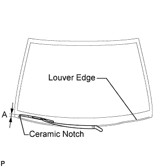
Install the front wiper arm and blade assembly RH with the nut to the position shown in the illustration.
- Torque:
- 26 N*m{265 kgf*cm, 19 ft.*lbf}
- HINT:
- Hold the arm hinge by hand while fastening the nut.
Area Measurement A 27.5 to 42.5 mm (1.08 to 1.67 in.)
 |
| 31. INSTALL FRONT WIPER ARM AND BLADE ASSEMBLY LH |
Operate the front wipers and stop the windshield wiper motor at the automatic stop position.
Clean the wiper arm serrations.
|
When reinstalling:
Clean the wiper pivot serrations with a wire brush.
Install the front wiper arm and blade assembly LH with the nut to the position shown in the illustration.
- Torque:
- 26 N*m{265 kgf*cm, 19 ft.*lbf}
- HINT:
- Hold the arm hinge by hand while fastening the nut.
Area Measurement A 31.5 to 46.5 mm (1.24 to 1.83 in.)
 |
Operate the front wipers while spraying washer fluid on the windshield glass. Make sure that the front wipers function properly and the wipers do not come into contact with the vehicle body.
| 32. INSTALL FRONT WIPER ARM HEAD CAP |
Install the 2 front wiper arm head caps.
 |
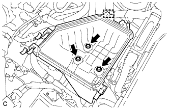
| 33. INSTALL AIR CLEANER CASE (for 2ZR-FE) |
Install the air cleaner case with the 3 bolts.
- Torque:
- 7.0 N*m{71 kgf*cm, 62 in.*lbf}
 |
Install the wire harness clamp to the air cleaner case.
Install the air cleaner filter element.
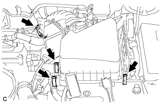
| 34. INSTALL AIR CLEANER CAP SUB-ASSEMBLY (for 2ZR-FE) |
Install the air cleaner cap sub-assembly with hose with the 2 clamps.
Tighten the hose clamp to the specified torque.
- Torque:
- 2.0 N*m{20 kgf*cm, 18 in.*lbf}
 |
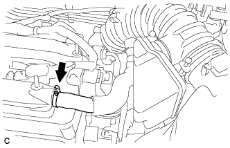
Connect the ventilation hose.
 |
Connect the 2 wire harness clamps and mass air flow meter connector.
 |
| 35. INSTALL NO. 2 CYLINDER HEAD COVER (for 2ZR-FE) |
Engage the 4 clips to install the No. 2 cylinder head cover.
- NOTICE:
- Be sure to engage the clips securely.
- Do not apply excessive force or do not hit the cover to engage the clips. This may cause the cover to break.
 |
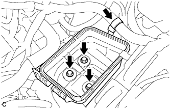
| 36. INSTALL AIR CLEANER CASE (for 2AZ-FE) |
Install the air cleaner case with the 3 bolts.
- Torque:
- 7.0 N*m{71 kgf*cm, 62 in.*lbf}
 |
Install the engine wire clamp to the air cleaner case.
Install the air cleaner filter element.
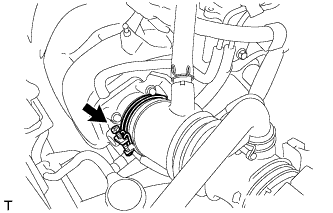
| 37. INSTALL AIR CLEANER CAP SUB-ASSEMBLY WITH HOSE (for 2AZ-FE) |
Install the air cleaner cap sub-assembly with hose and lock the 3 clamps.
 |
Tighten the air cleaner hose clamp.
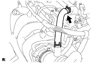
Connect the ventilation hose.
 |
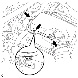
Connect the 2 vacuum hoses and No. 1 vacuum switching valve connector.
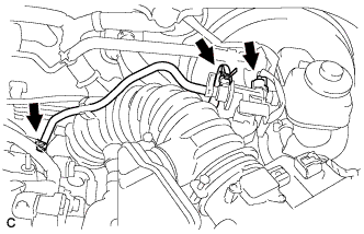 |
Connect the 2 wire harness clamps and the mass air flow meter connector.
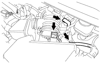 |
| 38. INSTALL NO. 1 ENGINE COVER SUB-ASSEMBLY (for 2AZ-FE) |
Install the No. 1 engine cover sub-assembly with the 2 nuts.
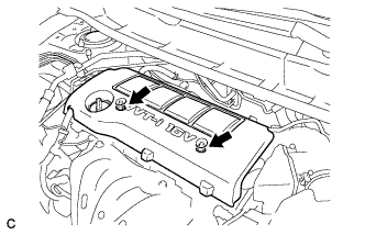 |