Shift And Select Lever Shaft Reassembly
INSTALL CONTROL SHAFT COVER OIL SEAL
INSTALL SELECT SPRING NO. 1 SEAT SHAFT SNAP RING
INSTALL NO. 1 SHIFT LEVER INNER
INSTALL SHIFT INTERLOCK PLATE COVER
INSTALL NO. 1 SELECT SPRING SEAT
INSTALL NO. 2 SHIFT LEVER INNER
INSTALL NO. 2 SELECTING BELLCRANK BUSHING
INSTALL NO. 2 SELECTING BELLCRANK DUST COVER
INSTALL SELECTING BELLCRANK SUPPORT SUB-ASSEMBLY
INSTALL NO. 1 SELECTING BELLCRANK DUST COVER
INSTALL CONTROL SHIFT LEVER BUSHING
Shift And Select Lever Shaft -- Reassembly |
| 1. INSTALL CONTROL SHAFT COVER OIL SEAL |
Using SST and a hammer, install a new control shaft cover oil seal to the control shaft cover.
- SST
- 09950-60010(09951-00280)
09950-70010(09951-07100)
- Oil seal installation depth:
- 28.0 to 29.0 mm (1.1024 to 1.142 in.)
| 2. INSTALL SELECT SPRING NO. 1 SEAT SHAFT SNAP RING |
Using a brass bar and a hammer, install the select spring No. 1 seat shaft snap ring.
| 3. INSTALL NO. 1 SHIFT LEVER INNER |
Install the No. 1 shift lever inner to the shift interlock plate.
| 4. INSTALL SHIFT INTERLOCK PLATE COVER |
Install the shift interlock plate cover to the shift interlock plate.
| 5. INSTALL NO. 1 SELECT SPRING SEAT |
Install the No. 1 select spring seat, No. 1 select return compression spring, and shift interlock plate to the shift and select lever shaft.
| 6. INSTALL NO. 2 SHIFT LEVER INNER |
Install the No. 2 shift lever inner, No. 2 select return compression spring and No. 2 select return spring seat to the shift and select lever shaft.
Hold the shift and select lever in a vise using aluminum plates.
Using a brass bar and a hammer, install the select seat snap ring to the shift and select lever shaft.
Using a pin punch (φ 5 mm) and a hammer, install the 2 shift inner lever slotted pins to the shift and select lever shaft.
- Clearance A:
- 0.7 to 1.7 mm (0.0276 to 0.0669 in.)
- Clearance B:
- -0.4 to 0.5 mm (-0.0157 to 0.0197 in.)
| 7. INSTALL NO. 2 SELECTING BELLCRANK BUSHING |
Coat the 2 No. 2 selecting bellcrank bushings with MP grease and install them to the No. 2 selecting bellcrank.
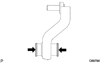
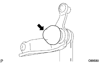
| 8. INSTALL NO. 2 SELECTING BELLCRANK DUST COVER |
Coat the No. 2 selecting bellcrank dust cover with MP grease and install it to the No. 2 selecting bellcrank.
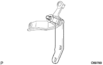
| 9. INSTALL SELECTING BELLCRANK SUPPORT SUB-ASSEMBLY |
Install the selecting bellcrank support sub-assembly to the No. 2 selecting bellcrank.
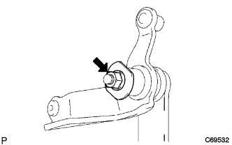
Install the No. 2 selecting bellcrank plate washer, wave washer, and nut.
- Torque:
- 12 N*m{122 kgf*cm, 9 ft.*lbf}
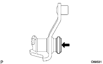
| 10. INSTALL NO. 1 SELECTING BELLCRANK DUST COVER |
Install the No. 1 selecting bellcrank dust cover to the No. 2 selecting bellcrank.
| 11. INSTALL CONTROL SHIFT LEVER BUSHING |
Install the control shift lever bushing to the No. 2 selecting bellcrank.