Manual Transaxle Unit Reassembly
INSTALL SYNCHRONIZER PULL RING
INSTALL NO. 3 SYNCHROMESH SHIFTING KEY SPRING
INSTALL TRANSAXLE CASE OIL SEAL
INSTALL FRONT DIFFERENTIAL CASE FRONT TAPERED ROLLER BEARING
INSTALL FRONT DIFFERENTIAL CASE REAR TAPERED ROLLER BEARING
INSTALL TRANSMISSION CASE OIL SEAL
INSTALL OUTPUT SHAFT REAR BEARING
INSTALL OUTPUT SHAFT COVER
INSTALL OUTPUT SHAFT FRONT BEARING
ADJUST OUTPUT SHAFT BEARING PRELOAD
ADJUST TAPERED ROLLER BEARING PRELOAD
INSTALL FRONT TRANSAXLE CASE COVER OIL SEAL
INSTALL INPUT SHAFT FRONT BEARING
INSTALL MANUAL TRANSAXLE CASE RECEIVER
INSTALL DIFFERENTIAL CASE ASSEMBLY
INSTALL OUTPUT SHAFT ASSEMBLY
INSTALL INPUT SHAFT ASSEMBLY
INSTALL NO. 2 GEAR SHIFT FORK
INSTALL NO. 3 GEAR SHIFT FORK
INSTALL NO. 1 GEAR SHIFT FORK
INSTALL NO. 2 GEAR SHIFT FORK SHAFT
INSTALL REVERSE SHIFT FORK ROLLER
INSTALL NO. 1 GEAR SHIFT FORK SHAFT
INSTALL REVERSE SHIFT ARM BRACKET ASSEMBLY
INSTALL REVERSE IDLER GEAR SUB-ASSEMBLY
INSTALL TRANSMISSION MAGNET
INSTALL NO. 1 OIL RECEIVER PIPE
INSTALL NO. 2 OIL RECEIVER PIPE
INSTALL REVERSE RESTRICT PIN ASSEMBLY
INSTALL MANUAL TRANSMISSION CASE
INSTALL REVERSE IDLER GEAR SHAFT BOLT
INSTALL SHIFT FORK SHAFT SNAP RING
INSTALL INPUT SHAFT REAR BEARING SHAFT SNAP RING
INSTALL OUTPUT SHAFT REAR BEARING SHIM
INSTALL REAR BEARING RETAINER
INSTALL 5TH DRIVEN GEAR
INSTALL 5TH GEAR NEEDLE ROLLER BEARING
INSTALL 5TH GEAR
INSTALL NO. 3 TRANSMISSION CLUTCH HUB
INSTALL MANUAL TRANSMISSION OUTPUT SHAFT REAR SET NUT
INSTALL MANUAL TRANSMISSION CASE COVER SUB-ASSEMBLY
INSTALL DRAIN PLUG SUB-ASSEMBLY
INSTALL MANUAL TRANSMISSION FILLER PLUG
INSTALL SHIFT AND SELECT LEVER SHAFT ASSEMBLY
INSTALL CONTROL SHAFT COVER
INSTALL BACK-UP LIGHT SWITCH ASSEMBLY
INSTALL MANUAL TRANSMISSION BREATHER PLUG
INSTALL SHIFT GATE PIN
INSTALL NO. 1 LOCK BALL ASSEMBLY
INSTALL NO. 2 CLUTCH TUBE BRACKET
INSTALL CONTROL SHIFT LEVER
INSTALL SELECTING BELLCRANK ASSEMBLY
INSTALL CONTROL CABLE BRACKET
INSTALL SPEEDOMETER DRIVEN HOLE COVER SUB-ASSEMBLY
INSTALL CLUTCH RELEASE FORK BOOT
INSTALL RELEASE FORK SUPPORT
INSTALL CLUTCH RELEASE BEARING ASSEMBLY
INSTALL CLUTCH RELEASE FORK SUB-ASSEMBLY
Manual Transaxle Unit -- Reassembly |
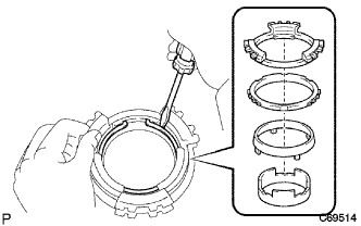
| 1. INSTALL SYNCHRONIZER PULL RING |
Install the No. 5 synchronizer ring middle, No. 5 synchronizer ring outer, and synchronizer pull ring to the No. 5 synchronizer ring inner. Using a screwdriver, secure them with the snap ring.
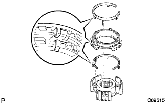
| 2. INSTALL NO. 3 SYNCHROMESH SHIFTING KEY SPRING |
Install the No. 3 synchromesh shifting key spring to the No. 3 transmission clutch hub.
- NOTICE:
- Align the projection of the shifting key spring with the hole of the No. 3 clutch hub.
Install the synchronizer ring set and No. 3 synchromesh shifting key spring to the No. 3 transmission clutch hub.
- NOTICE:
- Engage the shifting key spring claw to the center of the teeth of the synchronizer ring.
- Align the projection of the shifting key spring with the hole of the No. 3 clutch hub.
| 3. INSTALL TRANSAXLE CASE OIL SEAL |
Coat the new transaxle case oil seal lip with MP grease.
Using SST and a hammer, install a transaxle case oil seal.
- SST
- 09608-10010
09950-70010(09951-07200)
- Oil seal installation depth:
- -0.5 to 0.5 mm (-0.0197 to 0.0197 in.)
| 4. INSTALL FRONT DIFFERENTIAL CASE FRONT TAPERED ROLLER BEARING |
Using SST and a hammer, install the front differential case front tapered roller bearing (outer race) to the manual transaxle case.
- SST
- 09950-60020(09951-00910)
09950-70010(09951-07100)
Using SST and a press, install the front differential case front tapered roller bearing (inner race) to the front differential case.
- SST
- 09950-70010(09951-07100,09951-07150)
09608-10010
| 5. INSTALL FRONT DIFFERENTIAL CASE REAR TAPERED ROLLER BEARING |
Install the front differential case rear shim.
Using SST and a hammer, install the front differential case rear tapered roller bearing (outer race).
- SST
- 09950-60020(09951-00890)
09950-70010(09951-07100)
Using SST and a press, install the front differential case rear tapered roller bearing (inner race).
- SST
- 09631-12090
09950-60010(09951-00600)
09950-70010(09951-07100)
| 6. INSTALL TRANSMISSION CASE OIL SEAL |
Using SST and a hammer, install a new transmission case oil seal to the manual transmission case.
- SST
- 09608-32010
09950-70010(09951-07150)
- Oil seal installation depth:
- 3.0 to 4.0 mm (0.118 to 0.156 in.)
Coat the transmission case oil seal lip with MP grease.
| 7. INSTALL OUTPUT SHAFT REAR BEARING |
Using SST and a hammer, install the output shaft rear bearing (outer race) to the manual transmission case.
- SST
- 09950-60020(09951-00680)
09950-70010(09951-07100)
- Clearance:
- 3.8 to 4.4 mm (0.150 to 0.173 in.)
| 8. INSTALL OUTPUT SHAFT COVER |
Coat the output shaft cover with MP grease, and install it to the manual transaxle case.
- NOTICE:
- Align the projection of the output shaft cover with the transmission groove.
| 9. INSTALL OUTPUT SHAFT FRONT BEARING |
Using SST and a hammer, install the new output shaft front bearing (outer race).
- SST
- 09950-60020(09951-00730)
09950-70010(09951-07100)
| 10. ADJUST OUTPUT SHAFT BEARING PRELOAD |
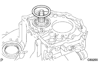
Install the output shaft to the manual transaxle case.
Install the transmission case to the manual transaxle case with the 14 bolts.
- Torque:
- 29 N*m{296 kgf*cm, 21 ft.*lbf}
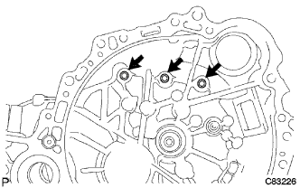
Install the 3 bolts to the manual transaxle case.
- Torque:
- 29 N*m{296 kgf*cm, 21 ft.*lbf}
Install the output shaft rear bearing case shim to the output shaft.
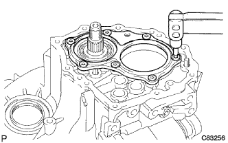
Using a "TORX" socket wrench (T45), install the rear bearing retainer to the manual transmission case with the 7 screws.
- Torque:
- 43 N*m{438 kgf*cm, 32 ft.*lbf}
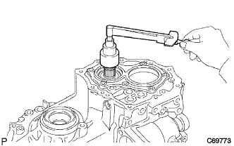
Turn the output shaft in both directions to make sure that it turns smoothly.
Using a socket wrench and torque wrench, inspect the preload.
- Preload:
Bearing
| Preload
N*m (kgf*cm, in.*lbf)
|
New
| 0.8 to 1.6 (8.16 to 16.32, 7.1 to 14.2)
|
Used
| 0.5 to 1.0 (5.10 to 10.20, 4.4 to 8.9)
|
|
|
If preload is not as specified, select a proper output shaft rear bearing shim and adjust it.
- HINT:
- The preload of all the output shaft rear bearing shim varies in torque from about 0.04 to 0.06 N*m (0.408 to 0.612 kgf*cm, 0.35 to 0.53 in.*lbf).
- Shim:
Part No.
| Thickness
mm (in.)
| Mark
|
90564-59001
| 1.30 (0.0512)
| 0
|
90564-59002
| 1.35 (0.0531)
| 1
|
90564-59003
| 1.40 (0.0551)
| 2
|
90564-59004
| 1.45 (0.0571)
| 3
|
90564-59005
| 1.50 (0.0591)
| 4
|
90564-59006
| 1.55 (0.0610)
| 5
|
90564-59007
| 1.60 (0.0630)
| 6
|
90564-59008
| 1.65 (0.0650)
| 7
|
90564-59009
| 1.70 (0.0669)
| 8
|
90564-59010
| 1.75 (0.0689)
| 9
|
90564-59011
| 1.80 (0.0709)
| A
|
90564-59012
| 1.85 (0.0728)
| B
|
90564-59013
| 1.90 (0.0748)
| C
|
90564-59014
| 1.95 (0.0768)
| D
|
90564-59015
| 2.00 (0.0787)
| E
|
90564-59016
| 2.05 (0.0807)
| F
|
90564-59017
| 2.10 (0.0827)
| G
|
90564-59018
| 2.15 (0.0846)
| H
|
90564-59019
| 2.20 (0.0866)
| J
|
90564-59020
| 2.25 (0.0886)
| K
|
90564-59021
| 2.30 (0.0906)
| L
|
90564-59022
| 2.35 (0.0925)
| M
|
90564-59023
| 2.40 (0.0945)
| N
|
90564-59024
| 2.45 (0.0965)
| P
|
90564-59025
| 2.50 (0.0984)
| Q
|
Remove the output shaft rear set nut from the output shaft.
Using a "TORX" socket wrench (T45), remove the 7 screws and rear bearing retainer from the manual transmission case.
Remove the output shaft rear bearing shim from the output shaft.
Remove the 3 bolts.
Remove the 14 bolts and manual transmission case from the manual transaxle case.
Remove the output shaft assembly from the front manual transaxle case.
| 11. ADJUST TAPERED ROLLER BEARING PRELOAD |
Install the differential case assembly to the manual transaxle case.
Install the 14 bolts and manual transmission case to the manual transaxle case.
- Torque:
- 29 N*m{296 kgf*cm, 21 ft.*lbf}
Install the 3 bolts to the manual transaxle case.
- Torque:
- 29 N*m{296 kgf*cm, 21 ft.*lbf}
Using SST, turn the differential in both directions to make sure that it turns smoothly.
- SST
- 09564-32011
Using SST and a torque wrench, inspect preload.
- SST
- 09564-32011
- Preload:
Bearing
| Preload
N*m (kgf*cm, in.*lbf)
|
New
| 0.8 to 1.6 (8.16 to 16.32, 7.1 to 14.2)
|
Used
| 0.5 to 1.0 (5.10 to 10.2, 4.4 to 8.9)
|
If preload is not as specified, select a proper front differential case rear shim and adjust it.
- HINT:
- The preload of all the front differential case rear shims varies in torque from about 0.04 to 0.06 N*m (0.408 to 0.612 kgf*cm, 0.35 to 0.53 in.*lbf).
- Shim:
Part No.
| Thickness
mm (in.)
| Mark
|
90564-56055
| 2.00 (0.0787)
| 0
|
90564-56056
| 2.05 (0.0807)
| 1
|
90564-56057
| 2.10 (0.0827)
| 2
|
90564-56058
| 2.15 (0.0846)
| 3
|
90564-56059
| 2.20 (0.0866)
| 4
|
90564-56060
| 2.25 (0.0886)
| 5
|
90564-56061
| 2.30 (0.0906)
| 6
|
90564-56062
| 2.35 (0.0925)
| 7
|
90564-56063
| 2.40 (0.0945)
| 8
|
90564-56064
| 2.45 (0.0965)
| 9
|
90564-56065
| 2.50 (0.0984)
| A
|
90564-56066
| 2.55 (0.1004)
| B
|
90564-56067
| 2.60 (0.1024)
| C
|
90564-56068
| 2.65 (0.1043)
| D
|
90564-56069
| 2.70 (0.1063)
| E
|
90564-56070
| 2.75 (0.1083)
| F
|
90564-56071
| 2.80 (0.1102)
| G
|
90564-56072
| 2.85 (0.1122)
| H
|
Remove the 3 bolts.
Remove the 14 bolts and manual transmission case from the manual transaxle case.
Remove the differential case assembly from the manual transaxle case.
| 12. INSTALL FRONT TRANSAXLE CASE COVER OIL SEAL |
Coat the lip of a new front transaxle case cover oil seal with MP grease.
Using SST and a hammer, install the new front transaxle case cover oil seal to the manual transaxle case.
- SST
- 09950-60010(09951-00420)
09950-70010(09951-07150)
- Clearance:
- 1.0 to 2.0 mm (0.0394 to 0.0787 in.)
| 13. INSTALL INPUT SHAFT FRONT BEARING |
Coat a new input shaft front bearing with gear oil.
Using SST and a hammer, install the bearing to the manual transaxle case.
- SST
- 09950-60010(09951-00570)
09950-70010(09951-07150)
- Clearance:
- 4.28 to 4.6 mm (0.169 to 0.181 in.)
| 14. INSTALL MANUAL TRANSAXLE CASE RECEIVER |
Install the manual transaxle case receiver to the manual transaxle case with the 3 bolts.
- Torque:
- 7.0 N*m{71 kgf*cm, 62 in.*lbf}
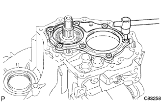
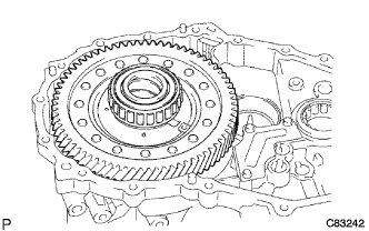
| 15. INSTALL DIFFERENTIAL CASE ASSEMBLY |
Coat the differential case tapered roller bearing with gear oil, and install the differential case assembly to the manual transaxle case.
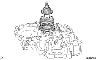
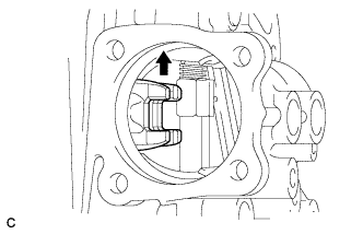
| 16. INSTALL OUTPUT SHAFT ASSEMBLY |
Apply gear oil to each sliding part of the output shaft assembly.
Lift the differential case assembly while tilting output shaft assembly, and install it to the manual transaxle case.
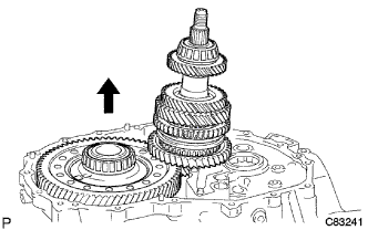
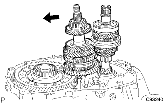
| 17. INSTALL INPUT SHAFT ASSEMBLY |
Apply gear oil to each sliding part of the input shaft assembly.
Install the input shaft assembly to the manual transaxle case while tilting the output shaft assembly.
| 18. INSTALL NO. 2 GEAR SHIFT FORK |
Coat the No. 2 gear shift fork with gear oil, and install it to the input shaft assembly.
| 19. INSTALL NO. 3 GEAR SHIFT FORK |
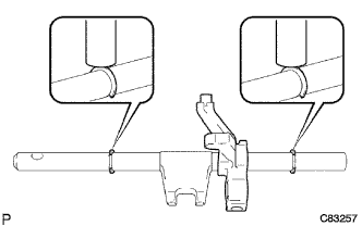
Install the No. 3 gear shift fork to the No. 3 gear shift fork shaft.
Using a brass bar and a hammer, install the 2 shift fork shaft snap rings to the gear shift fork shaft.
Apply gear oil to each sliding part of the No. 3 gear shift fork shaft, and install it to the manual transaxle case.
| 20. INSTALL NO. 1 GEAR SHIFT FORK |
Apply gear oil to each sliding part of the No. 1 gear shift fork, and install it to the output shaft assembly.
| 21. INSTALL NO. 2 GEAR SHIFT FORK SHAFT |
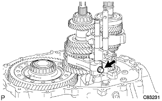
Install the No. 1 gear shift head to the No. 2 gear shift fork shaft.
Apply gear oil to each sliding part of the No. 2 gear shift fork shaft, and install it to the manual transaxle case.
Install the shift fork set bolt and shift head set bolt to the No. 1 gear shift head.
- Torque:
- 24 N*m{245 kgf*cm, 18 ft.*lbf}
| 22. INSTALL REVERSE SHIFT FORK ROLLER |
Using a magnetic pick-up tool, install the reverse shift fork roller to the reverse shift fork.
| 23. INSTALL NO. 1 GEAR SHIFT FORK SHAFT |
Using a brass bar and a hammer, install the shift fork shaft snap ring to the No. 1 shift fork shaft.
Install the No. 1 gear shift fork shaft to the manual transaxle case.
Install the shift fork set bolt to the No. 1 gear shift fork.
- Torque:
- 24 N*m{245 kgf*cm, 18 ft.*lbf}
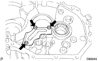
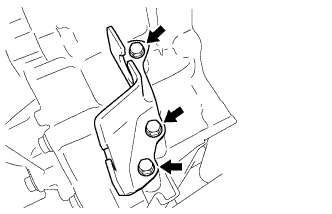
| 24. INSTALL REVERSE SHIFT ARM BRACKET ASSEMBLY |
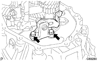
Install the reverse shift arm bracket assembly to the manual transaxle case with the 2 bolts.
- Torque:
- 17 N*m{173 kgf*cm, 13 ft.*lbf}
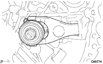
| 25. INSTALL REVERSE IDLER GEAR SUB-ASSEMBLY |
Coat the reverse idler gear and reverse idler thrust washer with MP grease, and install them to the reverse idler gear shaft.
Install the reverse idler gear to the manual transaxle case.
- HINT:
- Align the mark of the reverse idler gear shaft with the bolt hole.
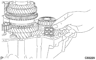
| 26. INSTALL TRANSMISSION MAGNET |
Clean the transmission magnet and install it to the manual transaxle case.
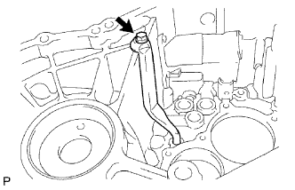
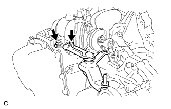
| 27. INSTALL NO. 1 OIL RECEIVER PIPE |
Install the No. 1 oil receiver pipe to the manual transmission case with the bolt.
- Torque:
- 17 N*m{173 kgf*cm, 13 ft.*lbf}
- NOTICE:
- Do not damage the pipe.
| 28. INSTALL NO. 2 OIL RECEIVER PIPE |
Install the No. 2 oil receiver pipe to the manual transmission case with the bolt.
- Torque:
- 17 N*m{173 kgf*cm, 13 ft.*lbf}
- NOTICE:
- Do not damage the pipe.
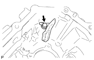
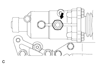
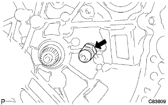
| 29. INSTALL REVERSE RESTRICT PIN ASSEMBLY |
Install the transmission oil baffle and reverse restrict pin with the bolt.
- Torque:
- 17 N*m{173 kgf*cm, 13 ft.*lbf}
Using a pin punch (φ 5 mm), install the slotted pin to the reverse restrict pin assembly.
- Clearance A:
- 12.5 to 13.5 mm (0.492 to 0.531 in.)
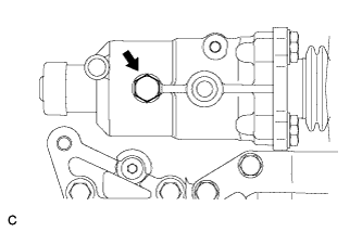
Coat the reverse restrict pin plug with adhesive. Using a hexagon wrench (6 mm), install the manual transmission case.
- Torque:
- 13 N*m{133 kgf*cm, 10 ft.*lbf}
- Adhesive:
- Toyota Genuine Adhesive 1324, Three Bond 1324 or equivalent
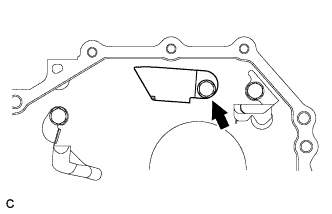
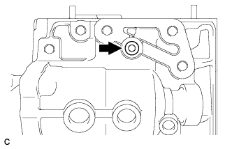
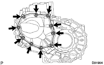
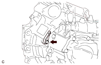
| 30. INSTALL MANUAL TRANSMISSION CASE |
Apply a bead of FIPG to the manual transmission case as shown in the illustration.
- HINT:
- Install the manual transmission case within 10 minutes after applying FIPG.
Install the manual transmission case to the manual transaxle case with the 14 bolts.
- Torque:
- 29 N*m{296 kgf*cm, 21 ft.*lbf}
Coat the 3 bolts with adhesive.
- Adhesive:
- Toyota Genuine Adhesive 1324, Three Bond 1324 or equivalent
Install the 3 bolts to the manual transaxle case.
- Torque:
- 29 N*m{296 kgf*cm, 21 ft.*lbf}
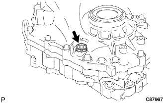
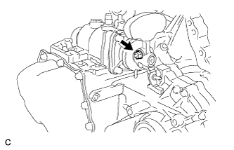
| 31. INSTALL REVERSE IDLER GEAR SHAFT BOLT |
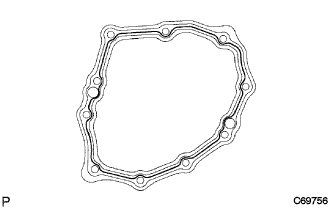
Coat the bolt with adhesive. Install a new gasket to the manual transmission case with the bolt.
- Torque:
- 30 N*m{306 kgf*cm, 22 ft.*lbf}
- Adhesive:
- Toyota Genuine Adhesive 1344, Three Bond 1344 or equivalent
| 32. INSTALL SHIFT FORK SHAFT SNAP RING |
Using a brass bar and a hammer, install the shift fork shaft snap ring to the No. 1 gear shift fork shaft.
Using a brass bar and a hammer, install the shift fork shaft snap ring to the No. 2 gear shift fork shaft.
| 33. INSTALL INPUT SHAFT REAR BEARING SHAFT SNAP RING |
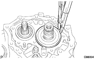
Using a snap ring expander, install the input shaft rear bearing shaft snap ring.
| 34. INSTALL OUTPUT SHAFT REAR BEARING SHIM |
Install the output shaft rear bearing shim to the output shaft.
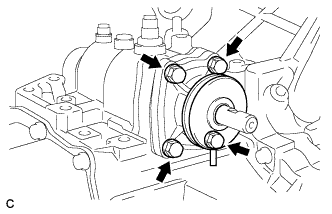
| 35. INSTALL REAR BEARING RETAINER |
Coat the 7 screws with adhesive.
- Adhesive:
- Toyota Genuine Adhesive 1344, Three Bond 1344 or equivalent
Using a "TORX" socket wrench (T45), install the rear bearing retainer to the manual transmission case with the 7 screws.
- Torque:
- 43 N*m{438 kgf*cm, 32 ft.*lbf}
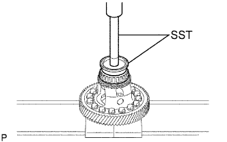
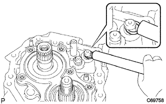
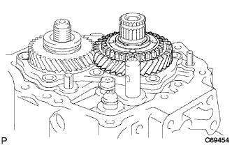
| 36. INSTALL 5TH DRIVEN GEAR |
Using SST, install the 5th driven gear to the output shaft.
- SST
- 09309-12020
| 37. INSTALL 5TH GEAR NEEDLE ROLLER BEARING |
Coat the 5th gear needle roller bearing with gear oil and install it to the input shaft.
Coat the 5th gear with gear oil and install it to the input shaft.
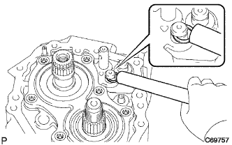
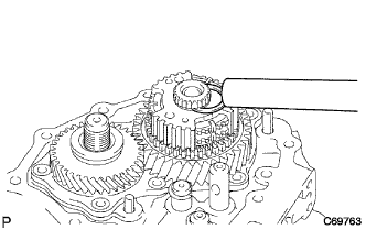
| 39. INSTALL NO. 3 TRANSMISSION CLUTCH HUB |
Using SST, install the No. 3 transmission clutch hub to the input shaft.
- SST
- 09950-30012(09951-03010,09953-03010,09954-03010)
- NOTICE:
- Align the projection of the synchronizer ring with the hole in the 5th gear.
Install the No. 3 transmission hub sleeve and No. 3 gear shift fork to the No. 3 transmission clutch hub.
Coat the shift fork set bolt with adhesive and install it to the No. 3 gear shift fork.
- Torque:
- 24 N*m{245 kgf*cm, 18 ft.*lbf}
- Adhesive:
- Toyota Genuine Adhesive 1344, Three Bond 1344 or equivalent
Select a snap ring that will allow minimal axial play. Using a brass bar and a hammer, install the shaft snap ring.
- Clearance:
- 0.1 mm (0.00394 in.) or less
- Snap Ring:
Part No.
| Thickness: mm (in.)
| Mark
|
90520-27061
| 1.75 to 1.80
(0.0689 to 0.0709)
| a
|
90520-27062
| 1.80 to 1.85
(0.0709 to 0.0728)
| b
|
90520-27063
| 1.85 to 1.90
(0.0728 to 0.0748)
| c
|
90520-27064
| 1.90 to 1.95
(0.0748 to 0.0768)
| d
|
90520-27065
| 1.95 to 2.00
(0.0768 to 0.0787)
| e
|
90520-27066
| 2.00 to 2.05
(0.0787 to 0.0807)
| f
|
90520-27067
| 2.05 to 2.10
(0.0807 to 0.0827)
| g
|
90520-27068
| 2.10 to 2.15
(0.0827 to 0.0846)
| h
|
90520-27069
| 2.15 to 2.20
(0.0846 to 0.0866)
| j
|
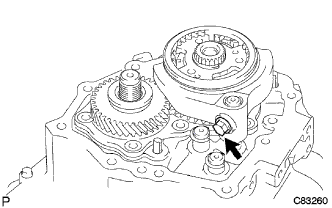
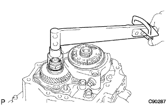
| 40. INSTALL MANUAL TRANSMISSION OUTPUT SHAFT REAR SET NUT |
Engage the 1st and 2nd gears simultaneously.
Install a new manual transmission output shaft rear set nut.
- Torque:
- 123 N*m{1254 kgf*cm, 90 ft.*lbf}
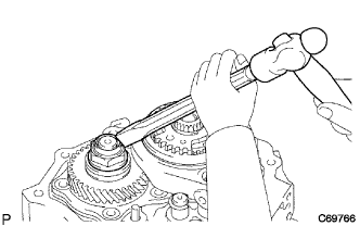
Using a chisel and a hammer, stake the manual transmission output shaft rear set nut.
Disengage the gears.
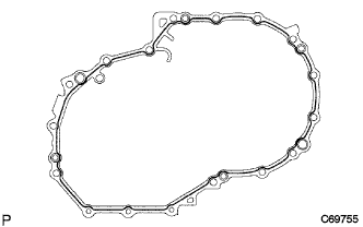
| 41. INSTALL MANUAL TRANSMISSION CASE COVER SUB-ASSEMBLY |
Apply FIPG to the manual transmission case cover sub-assembly as shown in the installation.
- FIPG:
- Toyota Genuine Seal Packing 1281, Three Bond 1281 or equivalent
- NOTICE:
- Install the part within 10 minutes after applying packing material (FIPG).
Install the manual transmission case cover sub-assembly to the manual transaxle case with the 10 bolts.
- Torque:
- 29 N*m{296 kgf*cm, 21 ft.*lbf}
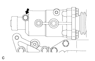
| 42. INSTALL DRAIN PLUG SUB-ASSEMBLY |
Install the drain plug sub-assembly to the manual transmission case with a new gasket.
- Torque:
- 49 N*m{500 kgf*cm, 36 ft.*lbf}
| 43. INSTALL MANUAL TRANSMISSION FILLER PLUG |
Install the manual transmission filler plug to the transaxle case with a new gasket.
- Torque:
- 49 N*m{500 kgf*cm, 36 ft.*lbf}
| 44. INSTALL SHIFT AND SELECT LEVER SHAFT ASSEMBLY |
Coat the shift and select lever shaft assembly with gear oil, and install it to the manual transmission case.
| 45. INSTALL CONTROL SHAFT COVER |
Coat the 4 bolts with adhesive. Install a new gasket and the control shaft cover with the bolts.
- Torque:
- 20 N*m{204 kgf*cm, 15 ft.*lbf}
- Adhesive:
- Toyota Genuine Adhesive 1344, Three Bond 1344 or equivalent
| 46. INSTALL BACK-UP LIGHT SWITCH ASSEMBLY |
Install the back-up light switch assembly to the manual transmission case with a new gasket.
- Torque:
- 40 N*m{408 kgf*cm, 30 ft.*lbf}
| 47. INSTALL MANUAL TRANSMISSION BREATHER PLUG |
Install the manual transmission breather plug to the manual transmission case.
| 48. INSTALL SHIFT GATE PIN |
Install the shift gate pin to the manual transmission case.
- Torque:
- 29 N*m{296 kgf*cm, 21 ft.*lbf}
| 49. INSTALL NO. 1 LOCK BALL ASSEMBLY |
Install the No. 1 lock ball assembly to the manual transmission case.
- Torque:
- 29 N*m{296 kgf*cm, 21 ft.*lbf}
| 50. INSTALL NO. 2 CLUTCH TUBE BRACKET |
Install the No. 2 clutch tube bracket with the bolt.
- Torque:
- 15 N*m{153 kgf*cm, 11 ft.*lbf}
| 51. INSTALL CONTROL SHIFT LEVER |
Install the control shift lever with the shift outer lever lock pin to the shift and select lever shaft.
Install the spring washer with the nut.
- Torque:
- 12 N*m{120 kgf*cm, 9 ft.*lbf}
| 52. INSTALL SELECTING BELLCRANK ASSEMBLY |
Coat the 2 bolts with adhesive. Install the selecting bellcrank assembly to the manual transmission case with the bolts.
- Torque:
- 20 N*m{204 kgf*cm, 15 ft.*lbf}
- Adhesive:
- Toyota Genuine Adhesive 1344, Three Bond 1344 or equivalent
| 53. INSTALL CONTROL CABLE BRACKET |
Install the control cable bracket to the manual transaxle case with the 3 bolts.
- Torque:
- 17 N*m{173 kgf*cm, 12 ft.*lbf}
| 54. INSTALL SPEEDOMETER DRIVEN HOLE COVER SUB-ASSEMBLY |
Install a new O-ring and the speedometer driven hole cover sub-assembly to the transmission case with the bolt.
- Torque:
- 5.5 N*m{56 kgf*cm, 48 in.*lbf}
| 55. INSTALL CLUTCH RELEASE FORK BOOT |
Install the clutch release fork boot to the manual transaxle case.
| 56. INSTALL RELEASE FORK SUPPORT |
Using a deep socket wrench, install the release fork support to the manual transaxle case.
- Torque:
- 47 N*m{480 kgf*cm, 36 ft.*lbf}
| 57. INSTALL CLUTCH RELEASE BEARING ASSEMBLY |
Coat the clutch release bearing assembly with release hub grease, and install it to the clutch release fork sub-assembly.
- Sealant:
- Toyota Genuine Release Hub Grease or equivalent
Apply clutch spline grease to the input shaft spline.
| 58. INSTALL CLUTCH RELEASE FORK SUB-ASSEMBLY |
Install the clutch release fork sub-assembly to the input shaft.