DESCRIPTION
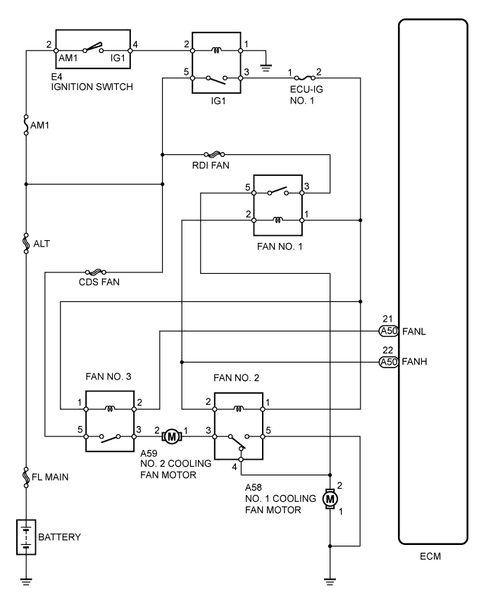
WIRING DIAGRAM
INSPECTION PROCEDURE
PERFORM ACTIVE TEST USING TECHSTREAM (OPERATE ELECTRIC COOLING FAN)
INSPECT ECM (FANL AND FANH VOLTAGE)
INSPECT ENGINE ROOM RELAY BLOCK (FAN NO. 1 RELAY AND FAN NO. 3 RELAY VOLTAGE)
INSPECT FAN NO. 1 RELAY
INSPECT FAN NO. 2 RELAY
INSPECT FAN NO. 3 RELAY
CHECK HARNESS AND CONNECTOR (ENGINE ROOM RELAY BLOCK - BODY GROUND)
INSPECT NO. 1 COOLING FAN MOTOR (RADIATOR FAN MOTOR)
CHECK HARNESS AND CONNECTOR (NO. 1 COOLING FAN MOTOR - BODY GROUND)
CHECK HARNESS AND CONNECTOR (NO. 1 COOLING FAN MOTOR - ENGINE ROOM RELAY BLOCK)
INSPECT NO. 2 COOLING FAN MOTOR (AIR CONDITIONER CONDENSER FAN MOTOR)
CHECK HARNESS AND CONNECTOR (NO. 2 COOLING FAN MOTOR - ENGINE ROOM RELAY BLOCK)
INSPECT ENGINE ROOM RELAY BLOCK (FAN NO. 1 RELAY - FAN NO. 2 RELAY)
CHECK FUSE (ECU-IG NO. 1 FUSE)
INSPECT FAN NO. 1 RELAY
INSPECT FAN NO. 2 RELAY
INSPECT FAN NO. 3 RELAY
CHECK HARNESS AND CONNECTOR (ENGINE ROOM RELAY BLOCK - ECM)
CHECK HARNESS AND CONNECTOR (ECU-IG NO. 1 FUSE - ENGINE ROOM RELAY BLOCK)
INSPECT FAN NO. 1 RELAY
INSPECT FAN NO. 3 RELAY
CHECK HARNESS AND CONNECTOR
COOLING FAN SYSTEM - Cooling Fan Circuit |
DESCRIPTION
The ECM turns on or off the fan relays using signals calculated from the engine coolant temperature, air conditioning (ON/OFF), air conditioner refrigerant pressure, engine speed, and vehicle speed signals.The ECM switches the circuit of the cooling fan motors between series and parallel by turning on or off the fan relays in order to control the speed of the cooling fan motors in two steps.
WIRING DIAGRAM
INSPECTION PROCEDURE
- NOTICE:
- After replacing the ECM, the new ECM needs registration (COROLLA_ZRE142 RM000000PDT0ANX.html).
| 1.PERFORM ACTIVE TEST USING TECHSTREAM (OPERATE ELECTRIC COOLING FAN) |
Connect the Techstream to the DLC3.
Turn the ignition switch to ON.
Turn the Techstream on.
Enter the following menus: Powertrain / Engine and ECT / Active Test / Control the Electric Cooling Fan.
- OK:
Techstream Operation
| Specified Condition
|
ON
| Fans operate
|
OFF
| Fans do not operate
|
- Result:
Result
| Proceed to
|
OK
| A
|
NG (Cooling fans do not operate)
| B
|
NG (Cooling fans do not stop)
| C
|
| 2.INSPECT ECM (FANL AND FANH VOLTAGE) |
Disconnect the ECM connector.
Turn the ignition switch to ON.
Measure the voltage according to the value(s) in the table below.
- Standard Voltage:
Tester Connection
| Switch Condition
| Specified Condition
|
A50-21 (FANL) - Body ground
| Ignition switch ON
| 11 to 14 V
|
A50-22 (FANH) - Body ground
| Ignition switch ON
| 11 to 14 V
|
Reconnect the ECM connector.
| 3.INSPECT ENGINE ROOM RELAY BLOCK (FAN NO. 1 RELAY AND FAN NO. 3 RELAY VOLTAGE) |
Remove the FAN No. 1 relay and FAN No. 3 relay from the engine room relay block.
Measure the voltage according to the value(s) in the table below.
- Standard Voltage:
Tester Connection
| Condition
| Specified Condition
|
3 (FAN No. 1 relay) - Body ground
| Always
| 11 to 14 V
|
5 (FAN No. 3 relay) - Body ground
| Always
| 11 to 14 V
|
Reinstall the FAN No. 1 relay and FAN No. 3 relay.
| | REPAIR OR REPLACE HARNESS OR CONNECTOR (BATTERY - ENGINE ROOM RELAY BLOCK) |
|
|
| 4.INSPECT FAN NO. 1 RELAY |
Inspect the FAN No. 1 relay (COROLLA_ZRE142 RM000000XX00AMX.html).
| 5.INSPECT FAN NO. 2 RELAY |
Inspect the FAN No. 2 relay (COROLLA_ZRE142 RM000000XX00AMX.html).
| 6.INSPECT FAN NO. 3 RELAY |
Inspect the FAN No. 3 relay (COROLLA_ZRE142 RM000000XX00AMX.html).
| 7.CHECK HARNESS AND CONNECTOR (ENGINE ROOM RELAY BLOCK - BODY GROUND) |
Remove the FAN No. 2 relay from the engine room relay block.
Measure the resistance according to the value(s) in the table below.
- Standard Resistance:
Tester Connection
| Condition
| Specified Condition
|
5 (FAN No. 2 relay) - Body ground
| Always
| Below 1 Ω
|
Reinstall the FAN No. 2 relay.
| | REPAIR OR REPLACE HARNESS OR CONNECTOR (ENGINE ROOM RELAY BLOCK - BODY GROUND) |
|
|
| 8.INSPECT NO. 1 COOLING FAN MOTOR (RADIATOR FAN MOTOR) |
Inspect the No. 1 cooling fan motor (COROLLA_ZRE142 RM000000YFJ0A9X.html).
| 9.CHECK HARNESS AND CONNECTOR (NO. 1 COOLING FAN MOTOR - BODY GROUND) |
Disconnect the No. 1 cooling fan motor (radiator fan motor) connector.
Measure the resistance according to the value(s) in the table below.
- Standard Resistance:
Tester Connection
| Condition
| Specified Condition
|
A58-1 - Body ground
| Always
| Below 1 Ω
|
Reconnect the No. 1 cooling fan motor connector.
| | REPAIR OR REPLACE HARNESS OR CONNECTOR (NO. 1 COOLING FAN MOTOR - BODY GROUND) |
|
|
| 10.CHECK HARNESS AND CONNECTOR (NO. 1 COOLING FAN MOTOR - ENGINE ROOM RELAY BLOCK) |
Disconnect the No. 1 cooling fan motor (radiator fan motor) connector.
Remove the FAN No. 1 relay and FAN No. 2 relay from the engine room relay block.
Measure the resistance according to the value(s) in the table below.
- Standard Resistance (Check for Open):
Tester Connection
| Condition
| Specified Condition
|
A58-2 - 5 (FAN No. 1 relay)
| Always
| Below 1 Ω
|
A58-2 - 4 (FAN No. 2 relay)
| Always
| Below 1 Ω
|
- Standard Resistance (Check for Short):
Tester Connection
| Condition
| Specified Condition
|
A58-2 or 5 (FAN No. 1 relay) - Body ground
| Always
| 10 kΩ or higher
|
A58-2 or 4 (FAN No. 2 relay) - Body ground
| Always
| 10 kΩ or higher
|
Reconnect the radiator fan motor connector.
Reinstall the FAN No. 1 relay and FAN No. 2 relay.
| | REPAIR OR REPLACE HARNESS OR CONNECTOR (NO. 1 COOLING FAN MOTOR - ENGINE ROOM RELAY BLOCK) |
|
|
| 11.INSPECT NO. 2 COOLING FAN MOTOR (AIR CONDITIONER CONDENSER FAN MOTOR) |
Inspect the No. 2 cooling fan motor (COROLLA_ZRE142 RM000000YFJ0A9X.html).
| 12.CHECK HARNESS AND CONNECTOR (NO. 2 COOLING FAN MOTOR - ENGINE ROOM RELAY BLOCK) |
Disconnect the No. 2 cooling fan motor (air conditioner condenser fan motor) connector.
Remove the FAN No. 2 relay and FAN No. 3 relay from the engine room relay block.
Measure the resistance according to the value(s) in the table below.
- Standard Resistance (Check for Open):
Tester Connection
| Condition
| Specified Condition
|
A59-1 - 3 (FAN No. 2 relay)
| Always
| Below 1 Ω
|
A59-2 - 3 (FAN No. 3 relay)
| Always
| Below 1 Ω
|
- Standard Resistance (Check for Short):
Tester Connection
| Condition
| Specified Condition
|
A59-1 or 3 (FAN No. 2 relay) - Body ground
| Always
| 10 kΩ or higher
|
A59-2 or 3 (FAN No. 3 relay) - Body ground
| Always
| 10 kΩ or higher
|
Reconnect the No. 2 cooling fan motor connector.
Reinstall the FAN No. 2 relay and FAN No. 3 relay.
| | REPAIR OR REPLACE HARNESS OR CONNECTOR (NO. 2 COOLING FAN MOTOR - ENGINE ROOM RELAY BLOCK) |
|
|
| 13.INSPECT ENGINE ROOM RELAY BLOCK (FAN NO. 1 RELAY - FAN NO. 2 RELAY) |
Remove the FAN No. 1 relay and FAN No. 2 relay from the engine room relay block.
Measure the resistance according to the value(s) in the table below.
- Standard Resistance (Check for Open):
Tester Connection
| Condition
| Specified Condition
|
1 (FAN No. 1 relay) - 1 (FAN No. 2 relay)
| Always
| Below 1 Ω
|
2 (FAN No. 1 relay) - 2 (FAN No. 2 relay)
| Always
| Below 1 Ω
|
- Standard Resistance (Check for Short):
Tester Connection
| Condition
| Specified Condition
|
1 (FAN No. 1 relay) or 1 (FAN No. 2 relay) - Body ground
| Always
| 10 kΩ or higher
|
2 (FAN No. 1 relay) or 2 (FAN No. 2 relay) - Body ground
| Always
| 10 kΩ or higher
|
Reinstall the FAN No. 1 relay and FAN No. 2 relay.
| | REPLACE ENGINE ROOM RELAY BLOCK |
|
|
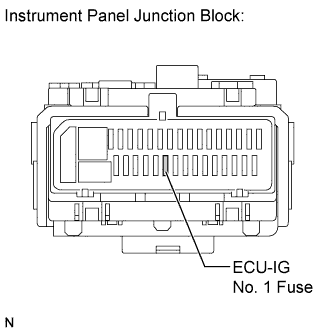
| 14.CHECK FUSE (ECU-IG NO. 1 FUSE) |
Remove the ECU-IG No. 1 fuse from the instrument panel junction block.
Measure the resistance according to the value(s) in the table below.
- Standard Resistance:
Tester Connection
| Condition
| Specified Condition
|
ECU-IG No. 1 fuse
| Always
| Below 1 Ω
|
Reinstall the ECU-IG No. 1 fuse.
| | REPLACE FUSE (ECU-IG NO. 1 FUSE) |
|
|
| 15.INSPECT FAN NO. 1 RELAY |
Inspect the FAN No. 1 relay (COROLLA_ZRE142 RM000000XX00AMX.html).
| 16.INSPECT FAN NO. 2 RELAY |
Inspect the FAN No. 2 relay (COROLLA_ZRE142 RM000000XX00AMX.html).
| 17.INSPECT FAN NO. 3 RELAY |
Inspect the FAN No. 3 relay (COROLLA_ZRE142 RM000000XX00AMX.html).
| 18.CHECK HARNESS AND CONNECTOR (ENGINE ROOM RELAY BLOCK - ECM) |
Remove the FAN No. 1 relay, FAN No. 2 relay and FAN No. 3 relay from the engine room relay block.
Disconnect the ECM connector.
Measure the resistance according to the value(s) in the table below.
- Standard Resistance (Check for Open):
Tester Connection
| Condition
| Specified Condition
|
2 (FAN No. 1 relay) - A50-22 (FANH)
| Always
| Below 1 Ω
|
2 (FAN No. 2 relay) - A50-22 (FANH)
| Always
| Below 1 Ω
|
2 (FAN No. 3 relay) - A50-21 (FANL)
| Always
| Below 1 Ω
|
Reinstall the FAN No. 1 relay, FAN No. 2 relay and FAN No. 3 relay.
Reconnect the ECM connector.
| | REPAIR OR REPLACE HARNESS OR CONNECTOR (ENGINE ROOM RELAY BLOCK - ECM) |
|
|
| 19.CHECK HARNESS AND CONNECTOR (ECU-IG NO. 1 FUSE - ENGINE ROOM RELAY BLOCK) |
Remove the FAN No. 1 relay, FAN No. 2 relay and FAN No. 3 relay from the engine room relay block.
Remove the ECU-IG No. 1 fuse from the instrument panel junction block.
Measure the resistance according to the value(s) in the table below.
- Standard Resistance (Check for Open):
Tester Connection
| Condition
| Specified Condition
|
1 (FAN No. 1 relay) - 2 (ECU-IG No. 1 fuse)
| Always
| Below 1 Ω
|
1 (FAN No. 2 relay) - 2 (ECU-IG No. 1 fuse)
| Always
| Below 1 Ω
|
1 (FAN No. 3 relay) - 2 (ECU-IG No. 1 fuse)
| Always
| Below 1 Ω
|
- Standard Resistance (Check for Short):
Tester Connection
| Condition
| Specified Condition
|
1 (FAN No. 1 relay) or 2 (ECU-IG No. 1 fuse) - Body ground
| Always
| 10 kΩ or higher
|
1 (FAN No. 2 relay) or 2 (ECU-IG No. 1 fuse) - Body ground
| Always
| 10 kΩ or higher
|
1 (FAN No. 3 relay) or 2 (ECU-IG No. 1 fuse) - Body ground
| Always
| 10 kΩ or higher
|
Reinstall the FAN No. 1 relay, FAN No. 2 relay and FAN No. 3 relay.
Reinstall the ECU-IG No. 1 fuse.
| | REPAIR OR REPLACE HARNESS OR CONNECTOR (ECU-IG NO. 1 FUSE - ENGINE ROOM RELAY BLOCK) |
|
|
| 20.INSPECT FAN NO. 1 RELAY |
Inspect the FAN No. 1 relay (COROLLA_ZRE142 RM000000XX00AMX.html).
| 21.INSPECT FAN NO. 3 RELAY |
Inspect the FAN No. 3 relay (COROLLA_ZRE142 RM000000XX00AMX.html).
| 22.CHECK HARNESS AND CONNECTOR |
Remove the FAN No. 1 relay, FAN No. 2 relay and FAN No. 3 relay from the engine room relay block.
Disconnect the ECM connector.
Measure the resistance according to the value(s) in the table below.
- Standard Resistance (Check for Short):
Tester Connection
| Condition
| Specified Condition
|
2 (FAN No. 1 relay) or A50-22 (FANH) - Body ground
| Always
| 10 kΩ or higher
|
2 (FAN No. 2 relay) or A50-22 (FANH) - Body ground
| Always
| 10 kΩ or higher
|
2 (FAN No. 3 relay) or A50-21 (FANL) - Body ground
| Always
| 10 kΩ or higher
|
Reinstall the FAN No. 1 relay, FAN No. 2 relay and FAN No. 3 relay.
Reconnect the ECM connector.
| | REPAIR OR REPLACE HARNESS OR CONNECTOR (ECU-IG NO. 1 FUSE - ENGINE ROOM RELAY BLOCK) |
|
|