Exhaust Manifold Installation
INSTALL NO. 1 MANIFOLD CONVERTER INSULATOR
INSTALL NO. 2 EXHAUST MANIFOLD HEAT INSULATOR
INSTALL EXHAUST MANIFOLD CONVERTER SUB-ASSEMBLY
INSTALL NO. 2 MANIFOLD STAY
INSTALL MANIFOLD STAY
INSTALL AIR FUEL RATIO SENSOR
INSTALL NO. 1 EXHAUST MANIFOLD HEAT INSULATOR
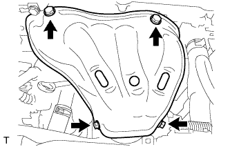
INSTALL FRONT EXHAUST PIPE ASSEMBLY
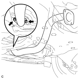
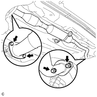
INSTALL CENTER EXHAUST PIPE ASSEMBLY
INSTALL GENERATOR ASSEMBLY
INSTALL V-RIBBED BELT
CONNECT CABLE TO NEGATIVE BATTERY TERMINAL
INSPECT FOR EXHAUST GAS LEAK
Exhaust Manifold -- Installation |
| 1. INSTALL NO. 1 MANIFOLD CONVERTER INSULATOR |
Install the No. 1 manifold converter insulator with the 4 bolts.
- Torque:
- 12 N*m{122 kgf*cm, 9 ft.*lbf}
| 2. INSTALL NO. 2 EXHAUST MANIFOLD HEAT INSULATOR |
Install the No. 2 exhaust manifold heat insulator with the 2 bolts.
- Torque:
- 12 N*m{122 kgf*cm, 9 ft.*lbf}
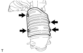
| 3. INSTALL EXHAUST MANIFOLD CONVERTER SUB-ASSEMBLY |
Install a new gasket.
Install the exhaust manifold converter sub-assembly with the 5 nuts in the order shown in the illustration.
- Torque:
- 37 N*m{377 kgf*cm, 27 ft.*lbf}
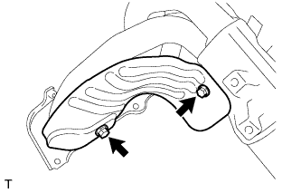
| 4. INSTALL NO. 2 MANIFOLD STAY |
Install the No. 2 manifold stay with the bolt and nut.
- Torque:
- 44 N*m{449 kgf*cm, 33 ft.*lbf}
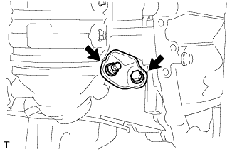
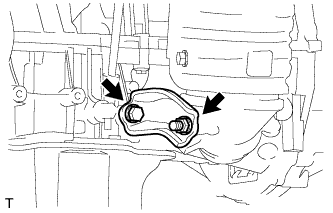
Install the manifold stay with the bolt and nut.
- Torque:
- 44 N*m{449 kgf*cm, 33 ft.*lbf}
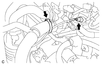
| 6. INSTALL AIR FUEL RATIO SENSOR |
Using SST, install the air fuel ratio sensor.
- SST
- 09224-00010
- Torque:
- without SST:
- 44 N*m{449 kgf*cm, 32 ft.*lbf}
- with SST:
- 40 N*m{408 kgf*cm, 30 ft.*lbf}
- NOTICE:
- This torque value can be obtained by using a torque wrench with a fulcrum length of 300 mm (11.81 in.) and SST with a measure of 30 mm (1.18 in.) (COROLLA_ZRE142 RM000000UYX0ETX.html).
- This torque value is effective when SST is parallel to the torque wrench.
Connect the air fuel ratio sensor connector and wire harness clamp.
| 7. INSTALL NO. 1 EXHAUST MANIFOLD HEAT INSULATOR |
Install the No. 1 exhaust manifold heat insulator with the 4 bolts.
- Torque:
- 12 N*m{122 kgf*cm, 9 ft.*lbf}
| 8. INSTALL FRONT EXHAUST PIPE ASSEMBLY |
Using a vernier caliper, measure the free length of the compression springs.
Minimum
| 41.5 mm (1.63 in.)
|
- HINT:
- If the free length is less than the minimum, replace the compression spring.
Remove the remains of exhaust manifold converter with wire brash.
Fully insert a new gasket to the exhaust manifold.
- NOTICE:
- Be sure to install the gasket in the correct direction.
- Do not reuse the gasket.
- Do not damage the gasket.
Install the front exhaust pipe assembly with the 2 bolts and 2 compression springs.
- Torque:
- 43 N*m{440 kgf*cm, 32 ft.*lbf}
Connect the heated oxygen sensor connector.
| 9. INSTALL CENTER EXHAUST PIPE ASSEMBLY |
Using a vernier caliper, measure the free length of the compression springs.
Minimum
| 38.5 mm (1.52 in.)
|
- HINT:
- If the free length is less than the minimum, replace the compression spring.
Fully insert a new gasket to the center exhaust pipe assembly.
- NOTICE:
- Be sure to install the gasket in the correct direction.
- Do not reuse the gasket.
- Do not damage the gasket.
Install a new gasket to the front exhaust pipe assembly.
Connect the center exhaust pipe assembly to the 2 exhaust pipe supports.
Install the center exhaust pipe assembly with the 4 bolts and 2 compression springs.
- Torque:
- 43 N*m{440 kgf*cm, 32 ft.*lbf}
| 10. INSTALL GENERATOR ASSEMBLY |
(COROLLA_ZRE142 RM0000026ZB01OX.html)
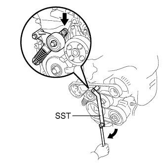
| 11. INSTALL V-RIBBED BELT |
- HINT:
- The illustration shows the V-ribbed belt layout.
Using SST, slowly turn the V-ribbed belt tensioner clockwise and install the V-ribbed belt.
- SST
- 09216-42010(09216-04010)
- NOTICE:
- Make sure that SST and other tools are set to the tensioner securely.
- When compressing the V-ribbed belt tensioner, slowly turn the tensioner.
| 12. CONNECT CABLE TO NEGATIVE BATTERY TERMINAL |
| 13. INSPECT FOR EXHAUST GAS LEAK |