Cylinder Block -- Inspection |
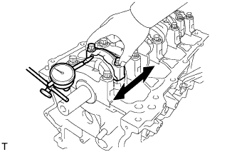
| 1. INSPECT CONNECTING ROD THRUST CLEARANCE |
Install the connecting rod cap (COROLLA_ZRE142 RM000002XA40C5X.html).
Using a dial indicator, measure the thrust clearance while moving the connecting rod back and forth.
- Standard thrust clearance:
- 0.160 to 0.342 mm (0.0063 to 0.0135 in.)
- Maximum thrust clearance:
- 0.342 mm (0.0135 in.)
 |
| 2. INSPECT CONNECTING ROD OIL CLEARANCE |
Clean the crank pin and bearing.
Check the crank pin and bearing for pitting and scratches.
Lay a strip of Plastigage on the crank pin.
 |
Check that the front mark of the connecting rod cap is facing forward.
 |
Install the connecting rod cap (COROLLA_ZRE142 RM000002XA40C5X.html).
- NOTICE:
- Do not turn the crankshaft.
Remove the 2 bolts and connecting rod cap (COROLLA_ZRE142 RM000002XA30BCX.html).
Measure the Plastigage at its widest point.
- Standard oil clearance:
- 0.030 to 0.062 mm (0.0012 to 0.0024 in.)
- Maximum oil clearance:
- 0.07 mm (0.0028 in.)
- NOTICE:
- Completely remove the Plastigage after the measurement.
- HINT:
- If replacing a bearing, replace it with one that has the same number as its respective connecting rod cap. Each standard bearing thickness is indicated by a 1, 2, or 3 mark on its surface.
- Standard Connecting Rod Large End Bore Diameter:
Mark Specified Condition Mark 1 47.000 to 47.008 mm (1.8504 to 1.8507 in.) Mark 2 47.009 to 47.016 mm (1.8507 to 1.8510 in.) Mark 3 47.017 to 47.024 mm (1.8511 to 1.8513 in.)
- Standard Connecting Rod Bearing Thickness:
Mark Specified Condition Mark 1 1.489 to 1.493 mm (0.0586 to 0.0588 in.) Mark 2 1.494 to 1.497 mm (0.0588 to 0.0589 in.) Mark 3 1.498 to 1.501 mm (0.0590 to 0.0591 in.)
- Standard Crankshaft Pin Diameter:
Mark Specified Condition Mark 1,2,3 43.992 to 44.000 mm (1.7320 to 1.7323 in.)
 |
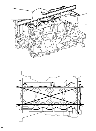
| 3. INSPECT CYLINDER BLOCK FOR WARPAGE |
Using a precision straightedge and feeler gauge, measure the warpage of the surface that is in contact with the cylinder head gasket.
- Maximum warpage:
- 0.05 mm (0.0020 in.)
 |
| 4. INSPECT CYLINDER BORE |
Using a cylinder gauge, measure the cylinder bore diameter at positions A and B in both thrust and axial directions.
- Standard diameter:
- 80.500 to 80.513 mm (3.1693 to 3.1698 in.)
- Maximum diameter:
- 80.633 mm (3.1745 in.)
 |
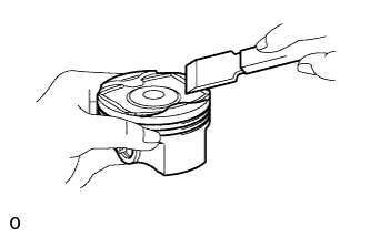
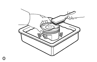
| 5. INSPECT PISTON |
Using a gasket scraper, remove the carbon from the top of the piston.
 |
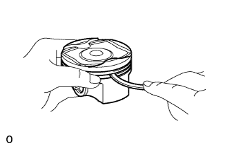
Using a groove cleaning tool or broken ring, clean the piston ring grooves.
 |
Using a brush and solvent, thoroughly clean the piston.
- NOTICE:
- Do not use a wire brush.
 |
Using a micrometer, measure the piston diameter at right angles to the piston pin hole, and at a point 12.6 mm (0.4961 in.) from the piston head.
- Standard piston diameter:
- 80.461 to 80.471 mm (3.1677 to 3.1681 in.)
 |
| 6. INSPECT PISTON OIL CLEARANCE |
Subtract the piston diameter measurement from the cylinder bore diameter measurement.
- Standard oil clearance:
- 0.029 to 0.052 mm (0.0011 to 0.0020 in.)
- Maximum oil clearance:
- 0.09 mm (0.0035 in.)
| 7. INSPECT RING GROOVE CLEARANCE |
Using a feeler gauge, measure the clearance between a new piston ring and the wall of the ring groove.
- Standard Ring Groove Clearance:
Item Specified Condition No. 1 Ring 0.02 to 0.07 mm (0.0008 to 0.0028 in.) No. 2 Ring 0.02 to 0.06 mm (0.0008 to 0.0024 in.) Oil Ring 0.02 to 0.065 mm (0.0008 to 0.0026 in.)
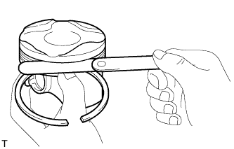 |
| 8. INSPECT PISTON RING END GAP |
Using a piston, push the piston ring a little beyond the bottom of the ring travel, 50 mm (1.97 in.) from the top of the cylinder block.
 |
Using a feeler gauge, measure the end gap.
- Standard End Gap:
Item Specified Condition No. 1 Ring 0.2 to 0.3 mm (0.0079 to 0.0118 in.) No. 2 Ring 0.3 to 0.5 mm (0.0118 to 0.0197 in.) Oil Ring 0.1 to 0.4 mm (0.0039 to 0.0157 in.)
- Maximum End Gap:
Item Specified Condition No. 1 Ring 0.5 mm (0.0197 in.) No. 2 Ring 0.7 mm (0.0276 in.) Oil Ring 0.7 mm (0.0276 in.)
 |
| 9. INSPECT PISTON PIN OIL CLEARANCE |
Using a caliper gauge, measure the piston pin bore diameter.
- Standard piston pin bore diameter:
- 20.006 to 20.015 mm (0.7876 to 0.7880 in.)
Item Specified Condition A 20.006 to 20.009 mm (0.7876 to 0.7878 in.) B 20.010 to 20.012 mm (0.7878 to 0.7879 in.) C 20.013 to 20.015 mm (0.7879 to 0.7880 in.)
 |
Using a micrometer, measure the piston pin diameter.
- Standard piston pin diameter:
- 20.004 to 20.013 mm (0.7876 to 0.7879 in.)
Item Specified Condition A 20.004 to 20.007 mm (0.7876 to 0.7877 in.) B 20.008 to 20.010 mm (0.7877 to 0.7878 in.) C 20.011 to 20.013 mm (0.7878 to 0.7879 in.)
 |
Using a caliper gauge, measure the connecting rod small end bore diameter.
- Standard connecting rod small end bore diameter:
- 20.012 to 20.021 mm (0.7879 to 0.7882 in.)
Item Specified Condition A 20.012 to 20.015 mm (0.7879 to 0.7880 in.) B 20.016 to 20.018 mm (0.7880 to 0.7881 in.) C 20.019 to 20.021 mm (0.7881 to 0.7882 in.)
 |
Subtract the piston pin diameter measurement from the piston pin bore diameter measurement.
- Standard oil clearance:
- -0.001 to 0.005 mm (-0.00004 to 0.0002 in.)
- Maximum oil clearance:
- 0.010 mm (0.0004 in.)
 |
Subtract the piston pin diameter measurement from the connecting rod small end bore diameter measurement.
- Standard oil clearance:
- 0.005 to 0.011 mm (0.0002 to 0.0004 in.)
- Maximum oil clearance:
- 0.014 mm (0.0006 in.)
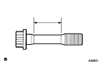
| 10. INSPECT CONNECTING ROD BOLT |
Using a vernier caliper, measure the tension portion diameter of the bolt.
- Standard diameter:
- 6.6 to 6.7 mm (0.2598 to 0.2638 in.)
- Minimum diameter:
- 6.4 mm (0.2520 in.)
 |
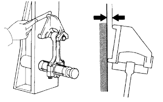
| 11. INSPECT CONNECTING ROD SUB-ASSEMBLY |
Using a connecting rod aligner and feeler gauge, check the connecting rod alignment.
Check for misalignment.
- Maximum misalignment:
- 0.05 mm (0.0020 in.) per 100 mm (3.94 in.)
Check for twist.
- Maximum twist:
- 0.15 mm (0.0059 in.) per 100 mm (3.94 in.)

 |
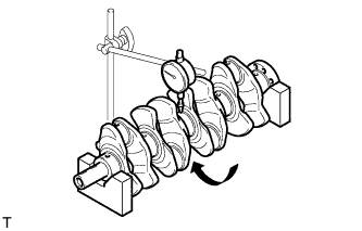
| 12. INSPECT CRANKSHAFT |
Using a dial indicator and V-blocks, measure the circle runout as shown in the illustration.
- Maximum circle runout:
- 0.03 mm (0.0012 in.)
 |
Using a micrometer, measure the diameter of each main journal.
- Standard diameter:
- 47.988 to 48.000 mm (1.8893 to 1.8898 in.)
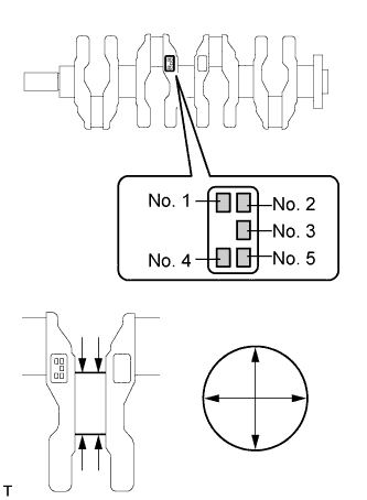 |
Check each main journal for taper and distortion as shown in the illustration.
- Maximum taper and distortion:
- 0.004 mm (0.0002 in.)
- Standard Diameter (Reference):
Mark Specified Condition 0 47.999 to 48.000 mm (1.8897 to 1.8898 in.) 1 47.997 to 47.998 mm (1.8896 to 1.8897 in.) 2 47.995 to 47.996 mm (1.8896 to 1.8896 in.) 3 47.993 to 47.994 mm (1.8895 to 1.8895 in.) 4 47.991 to 47.992 mm (1.8894 to 1.8894 in.) 5 47.988 to 47.990 mm (1.8893 to 1.8894 in.)
Using a micrometer, measure the diameter of each crank pin.
- Standard diameter:
- 43.992 to 44.000 mm (1.7320 to 1.7323 in.)
 |
Inspect each crank pin for taper and distortion as shown in the illustration.
- Maximum taper and distortion:
- 0.004 mm (0.0002 in.)
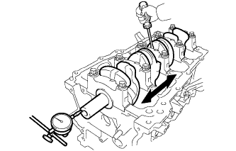
| 13. INSPECT CRANKSHAFT THRUST CLEARANCE |
Install the main bearing cap (COROLLA_ZRE142 RM000002XA40C5X.html).
Using a dial indicator, measure the thrust clearance while prying the crankshaft back and forth with a screwdriver.
- Standard thrust clearance:
- 0.04 to 0.14 mm (0.0016 to 0.0055 in.)
- Maximum thrust clearance:
- 0.18 mm (0.0071 in.)
- HINT:
- The thrust washer thickness is 2.43 to 2.48 mm (0.0957 to 0.0976 in.).
 |
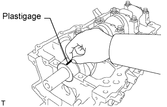
| 14. INSPECT CRANKSHAFT OIL CLEARANCE |
Check the crank journal and bearing for pitting and scratches.
Install the crankshaft bearing (COROLLA_ZRE142 RM000002XA40C5X.html).
Place the crankshaft on the cylinder block.
Lay a strip of Plastigage across each journal.
 |
Examine the front marks and numbers and install the bearing caps on the cylinder block.
- HINT:
- A number is marked on each main bearing cap to indicate the installation position.
Install the main bearing cap (COROLLA_ZRE142 RM000002XA40C5X.html).
- NOTICE:
- Do not turn the crankshaft.
Remove the main bearing caps (COROLLA_ZRE142 RM000002XA30BCX.html).
Measure the Plastigage at its widest point.

- Standard oil clearance:
- 0.016 to 0.039 mm (0.0006 to 0.0015 in.)
- Maximum oil clearance:
- 0.050 mm (0.0020 in.)
- NOTICE:
- Remove the Plastigage completely after the measurement.
- HINT:
- If replacing a bearing, select a new one with the same number. If the number of the bearing cannot be determined, calculate the correct bearing number by adding together the numbers imprinted on the cylinder block and crankshaft. Then select a new bearing with the calculated number according to the chart below. There are 4 sizes of standard bearings, marked "1", "2", "3" and "4" accordingly.
- EXAMPLE: Cylinder block "3" + Crankshaft "5" = Total number 8 (Use bearing "3")
Cylinder block + Crankshaft 0 to 2 3 to 5 6 to 8 9 to 11 Bearing to be used "1" "2" "3" "4" - Standard Cylinder Block Journal Bore Diameter:
Mark Specified Condition 0 52.000 to 52.003 mm (2.0472 to 2.0474 in.) 1 52.003 to 52.005 mm (2.04736 to 2.04744 in.) 2 52.005 to 52.007 mm (2.0474 to 2.0475 in.) 3 52.007 to 52.010 mm (2.0475 to 2.0476 in.) 4 52.010 to 52.012 mm (2.0476 to 2.0477 in.) 5 52.012 to 52.014 mm (2.0477 to 2.0478 in.) 6 52.014 to 52.016 mm (2.0478 to 2.0479 in.)
- Standard Crankshaft Journal Diameter:
Mark Specified Condition 0 47.999 to 48.000 mm (1.8897 to 1.8898 in.) 1 47.997 to 47.998 mm (1.8896 to 1.8897 in.) 2 47.995 to 47.996 mm (1.88956 to 1.88960 in.) 3 47.993 to 47.994 mm (1.8895 to 1.8895 in.) 4 47.991 to 47.992 mm (1.8894 to 1.8894 in.) 5 47.988 to 47.990 mm (1.8893 to 1.8894 in.)
- Standard Bearing Center Wall Thickness:
Mark Specified Condition 1 1.994 to 1.997 mm (0.0785 to 0.0786 in.) 2 1.998 to 2.000 mm (0.07866 to 0.07874 in.) 3 2.001 to 2.003 mm (0.0788 to 0.0789 in.) 4 2.004 to 2.006 mm (0.0789 to 0.0790 in.)
| 15. INSPECT CYLINDER HEAD SET BOLT |
Using a vernier caliper, measure the tension portion diameter of the bolts.
- Standard bolt length:
- 84.3 to 85.7 mm (3.3189 to 3.3740 in.)
- Maximum bolt length:
- 86.7 mm (3.4134 in.)
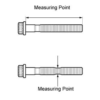 |
Using a vernier caliper, measure the minimum diameter of the elongated thread at the measuring point.
- Standard outside diameter:
- 9.77 to 9.96 mm (0.3846 to 0.3921 in.)
- Minimum outside diameter:
- 9.1 mm (0.3583 in.)
- HINT:
- Using a straightedge, visually check thinner areas of the threaded part of the crankshaft bearing cap bolt.
| 16. INSPECT NO. 1 OIL NOZZLE SUB-ASSEMBLY |
Check the oil nozzles for damage or clogging.
- HINT:
- If there is damage or clogging, replace the oil nozzle.