Engine Unit -- Inspection |
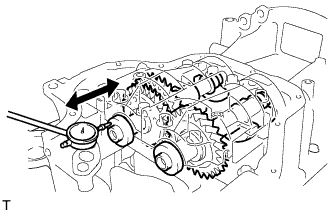
| 1. INSPECT BALANCESHAFT THRUST CLEARANCE |
Install the balanceshafts (COROLLA_ZRE142 RM00000224800UX.html).
Using a dial indicator, measure the thrust clearance while moving the balanceshaft back and forth.
- Standard thrust clearance:
- 0.05 to 0.09 mm (0.0020 to 0.0035 in.)
- Maximum thrust clearance:
- 0.09 mm (0.0035 in.)
 |
| 2. INSPECT BALANCESHAFT OIL CLEARANCE |
Clean each bearing and journal.
Check each bearing and journal for pitting and scratches.
If a bearing or journal is damaged, replace the bearings. If necessary, replace the balanceshaft.
Place the No. 1 and No. 2 balanceshafts onto the crankcase.
Lay a strip of Plastigage across each journal.
 |
Install the balanceshaft housing (COROLLA_ZRE142 RM00000224800UX.html).
- NOTICE:
- Do not turn the balanceshafts.
Remove the balanceshafts (COROLLA_ZRE142 RM00000224700UX.html).
Measure the Plastigage at its widest point.
- Standard oil clearance:
- 0.022 to 0.049 mm (0.0009 to 0.0019 in.)
- Maximum oil clearance:
- 0.049 mm (0.0019 in.)
- NOTICE:
- Remove the Plastigage completely after the measurement.
 |
If replacing a bearing, select a new one with the same number.
- Standard Balanceshaft Housing Journal Bore Diameter:
Item Specified Condition Mark 1 26.000 to 26.006 mm (1.0236 to 1.0239 in.) Mark 2 26.007 to 26.012 mm (1.0239 to 1.0241 in.) Mark 3 26.013 to 26.018 mm (1.0241 to 1.0243 in.)
- Standard Bearing Center Wall Thickness:
Item Specified Condition Mark 1 1.486 to 1.489 mm (0.05850 to 0.05862 in.) Mark 2 1.490 to 1.492 mm (0.05866 to 0.05874 in.) Mark 3 1.493 to 1.495 mm (0.0588 to 0.0589 in.)
- Standard balanceshaft journal diameter:
- 22.985 to 23.000 mm (0.9049 to 0.9055 in.)
 |
Inspect the balanceshaft housing bolts.
Using a vernier caliper, measure the length of the bolts from the seat to the end.
- Standard bolt length:
- 58.3 to 59.7 mm (2.295 to 2.350 in.)
- Maximum bolt length:
- 60.3 mm (2.374 in.)

| 3. INSPECT CHAIN SUB-ASSEMBLY |
Pull the chain with a force of 140 N (14.3 kgf, 31.5 lbf) as shown in the illustration.
 |
Using a vernier caliper, measure the length of 15 links.
- Maximum chain elongation:
- 114.5 mm (4.508 in.)
- NOTICE:
- Perform the measurement at 3 random places. Use the average of the measurements.
| 4. INSPECT NO. 2 CHAIN SUB-ASSEMBLY |
Pull the chain with a force of 140 N (14.3 kgf, 31.5 lbf) as shown in the illustration.
|
Using a vernier caliper, measure the length of 15 links.
- Maximum chain elongation:
- 102.2 mm (4.024 in.)
- NOTICE:
- Perform the measurement at 3 random places. Use the average of the measurements.
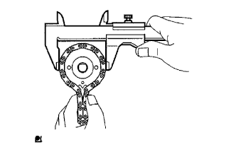
| 5. INSPECT OIL PUMP DRIVE GEAR |
Wrap the chain around the sprocket.
 |
Using a vernier caliper, measure the sprocket diameter with the chain wrapped around.
- Minimum gear diameter (with chain):
- 48.2 mm (1.898 in.)
- NOTICE:
- The vernier caliper must be in contact with the chain rollers when measuring.
| 6. INSPECT OIL PUMP DRIVE SHAFT GEAR |
Wrap the chain around the sprocket.
 |
Using a vernier caliper, measure the sprocket diameter with the chain wrapped around.
- Minimum gear diameter (with chain):
- 48.2 mm (1.898 in.)
- NOTICE:
- The vernier caliper must be in contact with the chain rollers when measuring.
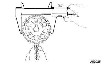
| 7. INSPECT CAMSHAFT TIMING GEAR ASSEMBLY |
Wrap the chain around the sprocket.
 |
Using a vernier caliper, measure the sprocket diameter with the chain wrapped around.
- Minimum gear diameter (with chain):
- 97.3 mm (3.831 in.)
- NOTICE:
- The vernier caliper must be in contact with the chain rollers when measuring.
| 8. INSPECT CAMSHAFT TIMING GEAR OR SPROCKET |
Wrap the chain around the sprocket.
 |
Using a vernier caliper, measure the sprocket diameter with the chain wrapped around.
- Minimum gear diameter (with chain):
- 97.3 mm (3.831 in.)
- NOTICE:
- The vernier caliper must be in contact with the chain rollers when measuring.
| 9. INSPECT CRANKSHAFT TIMING GEAR OR SPROCKET |
Wrap the chain around the timing sprocket.
|
Using a vernier caliper, measure the timing gear diameter with the chain wrapped around.
- Minimum gear diameter (with chain):
- 51.6 mm (2.031 in.)
- NOTICE:
- The vernier caliper must be in contact with the chain rollers when measuring.
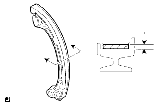
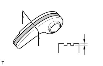
| 10. INSPECT CHAIN TENSIONER SLIPPER |
Using a vernier caliper, measure the tensioner slipper wear.
- Maximum wear:
- 1.0 mm (0.039 in.)
 |
| 11. INSPECT NO. 1 CHAIN VIBRATION DAMPER |
Using a vernier caliper, measure the vibration damper wear.
- Maximum wear:
- 1.0 mm (0.039 in.)
 |
| 12. INSPECT CHAIN TENSIONER PLATE |
Using a vernier caliper, measure the vibration damper wear.
- Maximum wear:
- 0.5 mm (0.020 in.)
 |
| 13. INSPECT NO. 1 CHAIN TENSIONER ASSEMBLY |
Check that the plunger moves smoothly when the ratchet pawl is raised with your finger.
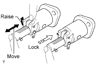 |
Release the ratchet pawl, then check that the plunger is locked in place by the ratchet pawl and does not move when pushed with your finger.
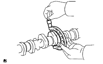
| 14. INSPECT CAMSHAFT |
Inspect the camshaft for runout.
Place the camshaft on V-blocks.
Using a dial indicator, measure the circle runout at the center journal.
- Maximum circle runout:
- 0.03 mm (0.0012 in.)
 |
Inspect the cam lobes.
Using a micrometer, measure the cam lobe heights.
- Standard cam lobe height:
- 47.306 to 47.406 mm (1.8624 to 1.8664 in.)
- Minimum cam lobe height:
- 47.196 mm (1.8581 in.)
 |
Inspect the camshaft journals.
Using a micrometer, measure the journal diameter.
- Standard Journal Diameter:
Journal Position Specified Condition No. 1 35.971 to 35.985 mm (1.4162 to 1.4167 in.) Others 22.959 to 22.975 mm (0.9039 to 0.9045 in.)
 |
| 15. INSPECT NO. 2 CAMSHAFT |
Inspect the camshaft for runout.
Place the camshaft on V-blocks.
Using a dial indicator, measure the circle runout at the center journal.
- Maximum circle runout:
- 0.03 mm (0.0012 in.)
|
Inspect the cam lobes.
Using a micrometer, measure the cam lobe heights.
- Standard cam lobe height:
- 46.063 to 46.163 mm (1.8135 to 1.8174 in.)
- Minimum cam lobe height:
- 45.953 mm (1.8092 in.)
|
Inspect the camshaft journals.
Using a micrometer, measure the journal diameter.
- Standard Journal Diameter:
Journal Position Specified Condition No. 1 35.971 to 35.985 mm (1.4162 to 1.4167 in.) Others 22.959 to 22.975 mm (0.9039 to 0.9045 in.)
|