INSTALL FUEL DELIVERY PIPE SUB-ASSEMBLY WITH FUEL TUBE SUB-ASSEMBLY
INSTALL SUSPENSION TOWER DAMPER ASSEMBLY (w/ Front Strut Bar)
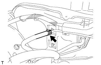
Knock Sensor -- Installation |
| 1. INSTALL KNOCK SENSOR |
Install the knock sensor with the nut.
- Torque:
- 20 N*m{204 kgf*cm, 15 ft.*lbf}
 |
Connect the sensor connector.
| 2. INSTALL NO. 1 INTAKE MANIFOLD INSULATOR |
Install the No. 1 intake manifold insulator.
| 3. INSTALL INTAKE MANIFOLD |
 |
Install a new gasket to the intake manifold.
Install the intake manifold with the 5 bolts and 2 nuts.
- Torque:
- 30 N*m{306 kgf*cm, 22 ft.*lbf}
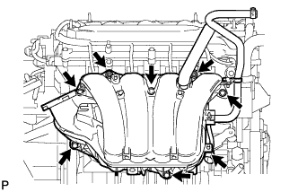 |
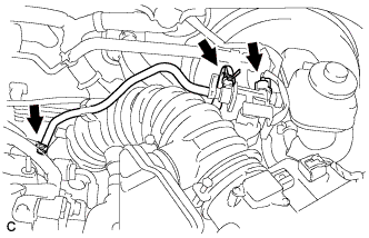
Install the wire harness clamp onto the intake manifold.
Connect the union to check valve hose.
 |
Connect the ventilation hose.
 |
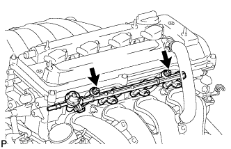
| 4. INSTALL FUEL DELIVERY PIPE SUB-ASSEMBLY WITH FUEL TUBE SUB-ASSEMBLY |
Install 4 new insulators to the cylinder head.
 |
Install the 2 delivery pipe spacers onto the cylinder head.
Install the fuel delivery pipe together with the 4 fuel injectors, then temporarily tighten the 2 bolts.
- NOTICE:
- Be careful not to drop the fuel injectors when installing the fuel delivery pipe.
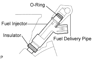 |
Check that the fuel injector rotates smoothly.
If the fuel injector does not rotate smoothly, replace the O-ring.
Tighten the 2 bolts to the specified torque.
- Torque:
- 20 N*m{205 kgf*cm, 15 ft.*lbf}
 |
Connect the 4 fuel injector connectors.
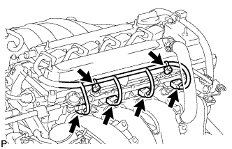 |
Install the 2 wire harness clamps.
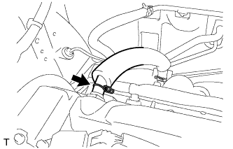
| 5. CONNECT FUEL TUBE SUB-ASSEMBLY |
Connect the fuel main tube.
Push the fuel tube connector until it makes a "click" sound.
Install the fuel pipe clamp.
Install the fuel tube to the fuel hose clamp.
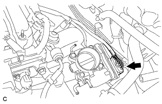
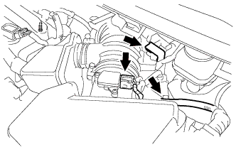
| 6. INSTALL THROTTLE BODY ASSEMBLY |
Install a new gasket onto the intake manifold.
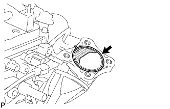 |
Install the throttle body assembly with the 4 bolts.
- Torque:
- 30 N*m{306 kgf*cm, 22 ft.*lbf}
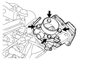 |
Connect the throttle body connector.
 |
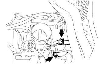
Connect the 2 water by-pass hoses.
 |
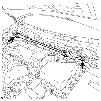
| 7. INSTALL SUSPENSION TOWER DAMPER ASSEMBLY (w/ Front Strut Bar) |
Fully tighten the 2 nuts.
- Torque:
- 52 N*m{530 kgf*cm, 38 ft.*lbf}
 |
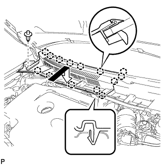
| 8. INSTALL OUTER COWL TOP PANEL |
Install the outer cowl top panel with the 12 bolts.
- Torque:
- 8.8 N*m{90 kgf*cm, 78 in.*lbf}
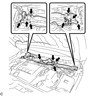 |
Engage the clamp.
Bend the water guard plate RH as shown in the illustration and engage the clamp.
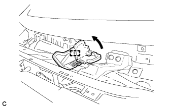 |
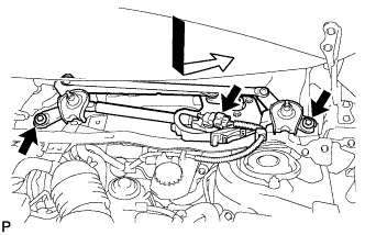
| 9. INSTALL WINDSHIELD WIPER MOTOR AND LINK ASSEMBLY |
Install the windshield wiper motor and link assembly with the 2 bolts.
- Torque:
- 5.5 N*m{56 kgf*cm, 49 in.*lbf}
 |
Connect the connector.
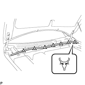
| 10. INSTALL COWL TOP VENTILATOR LOUVER LH |
Engage the clip and 8 claws to install the cowl top ventilator louver LH.
 |
| 11. INSTALL CENTER NO. 1 COWL TOP VENTILATOR LOUVER |
Engage the clip and 14 claws to install the center No. 1 cowl top ventilator louver.
 |
| 12. INSTALL HOOD TO COWL TOP SEAL |
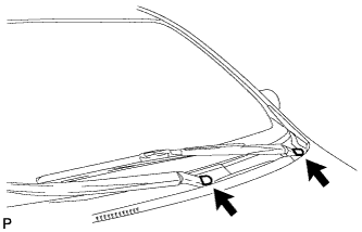
Engage the 7 clips to install the hood to cowl top seal.
 |
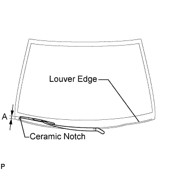
| 13. INSTALL FRONT WIPER ARM AND BLADE ASSEMBLY RH |
Operate the wiper and stop the windshield wiper motor at the automatic stop position.
Clean the wiper arm serrations.
 |
When reinstalling:
Clean the wiper pivot serrations with a wire brush.
Install the front wiper arm and blade assembly RH with the nut to the position shown in the illustration.
- Torque:
- 26 N*m{265 kgf*cm, 19 ft.*lbf}
- HINT:
- Hold the arm hinge by hand while fastening the nut.
Area Measurement A 27.5 to 42.5 mm (1.08 to 1.67 in.)
 |
| 14. INSTALL FRONT WIPER ARM AND BLADE ASSEMBLY LH |
Operate the front wipers and stop the windshield wiper motor at the automatic stop position.
Clean the wiper arm serrations.
|
When reinstalling:
Clean the wiper pivot serrations with a wire brush.
Install the front wiper arm and blade assembly LH with the nut to the position shown in the illustration.
- Torque:
- 26 N*m{265 kgf*cm, 19 ft.*lbf}
- HINT:
- Hold the arm hinge by hand while fastening the nut.
Area Measurement A 31.5 to 46.5 mm (1.24 to 1.83 in.)
 |
Operate the front wipers while spraying washer fluid on the windshield glass. Make sure that the front wipers function properly and the wipers do not come into contact with the vehicle body.
| 15. INSTALL FRONT WIPER ARM HEAD CAP |
Install the 2 front wiper arm head caps.
 |
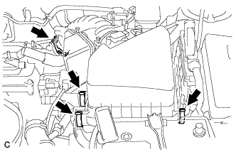
| 16. INSTALL AIR CLEANER CAP SUB-ASSEMBLY WITH HOSE |
Install the air cleaner cap sub-assembly with hose and lock the 3 clamps.
 |
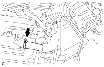
Tighten the air cleaner hose clamp.
Connect the ventilation hose.
 |
Connect the 2 vacuum hoses and No. 1 vacuum switching valve connector.
 |
Connect the 2 wire harness clamps and the mass air flow meter connector.
 |
| 17. ADD ENGINE COOLANT |
Tighten the lower radiator drain cock plug.
Tighten the cylinder block drain cock plug.
- Torque:
- 13 N*m{130 kgf*cm, 9 ft.*lbf}
Loosen the upper radiator drain cock plug.
Slowly fill the radiator with TOYOTA Super Long Life Coolant (SLLC).
- Standard Capacity:
Item Capacity Engine coolant 5.7 liters (6.0 US qts, 5.0 lmp. qts)
- HINT:
- TOYOTA vehicles are filled with TOYOTA SLLC at the factory. In order to avoid damage to the engine cooling system and other technical problems, only use TOYOTA SLLC or similar high quality ethylene glycol based non-silicate, non-amine, non-nitrite, non-borate coolant with long-life hybrid organic acid technology (coolant with long-life hybrid organic acid technology consists of a combination of low phosphates and organic acids).
- Contact your TOYOTA dealer for further details.
- NOTICE:
- Never use water as a substitute for engine coolant.
Squeeze the inlet and outlet radiator hoses several times by hand, and then check the level of the coolant.
If the coolant level is low, add coolant.
Tighten the upper radiator drain cock plug.
Slowly pour coolant into the radiator reservoir tank until it reaches the FULL line.
Install the radiator cap sub-assembly and reservoir tank cap.
Start the engine and warm it up.
Bleed air from the cooling system.
- NOTICE:
- Before starting the engine, turn the A/C switch off.
- Adjust the air conditioning temperature setting to MAX (HOT).
- Adjust the air conditioning blower setting to LO.
Warm up the engine until the thermostat opens. While the thermostat is open, allow the coolant to circulate for several minutes.
- HINT:
- Thermostat opening timing can be determined by squeezing the inlet radiator hose, and sensing vibrations when the engine coolant starts to flow inside the hose.
- CAUTION:
- When squeezing the radiator hoses:
- Wear protective gloves.
- Be careful as the radiator hoses are hot.
- Keep your hands away from the radiator fan.
Stop the engine, and wait until the engine coolant cools down.
Add engine coolant to the FULL line on the radiator reservoir.
| 18. INSPECT FOR COOLANT LEAK |
 |
- CAUTION:
- To avoid the danger of being burned, do not remove the radiator cap sub-assembly while the engine and radiator assembly are still hot. Thermal expansion will cause hot engine coolant and steam to blow out from the radiator assembly.
Fill the radiator assembly with engine coolant, then attach a radiator cap tester.
Pump the tester to 118 kPa (1.2 kgf/cm2, 17.1 psi), then check that the pressure does not drop.
If the pressure drops, check the hoses, radiator assembly and water pump assembly for leakage. If there are no signs or traces of external engine coolant leakage, check the heater core, cylinder block and head.
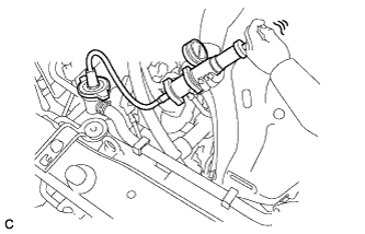
| 19. INSPECT FOR FUEL LEAK |
Check fuel pump operation.
Connect the Techstream to the DLC3.
Turn the ignition switch to ON and turn the Techstream on.
- NOTICE:
- Do not start the engine.
Enter the following menus: Powertrain / Engine and ECT / Active Test / Control the Fuel Pump / Speed.
Check for pressure in the fuel inlet tube from the fuel line. Check that sounds of fuel flowing from the fuel tank can be heard. If no sounds can be heard, check the integration relay, fuel pump, ECM and wiring connectors.
Check for fuel leaks.
There is no fuel leakage after performing maintenance anywhere on the fuel system. If there is a fuel leak, repair or replace parts as necessary.
Turn the ignition switch off.
Disconnect the Techstream from the DLC3.
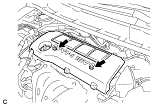
| 20. INSTALL NO. 1 ENGINE COVER SUB-ASSEMBLY |
Install the No. 1 engine cover sub-assembly with the 2 nuts.
 |