Can Communication System (For Rhd) Can Bus Line
DESCRIPTION
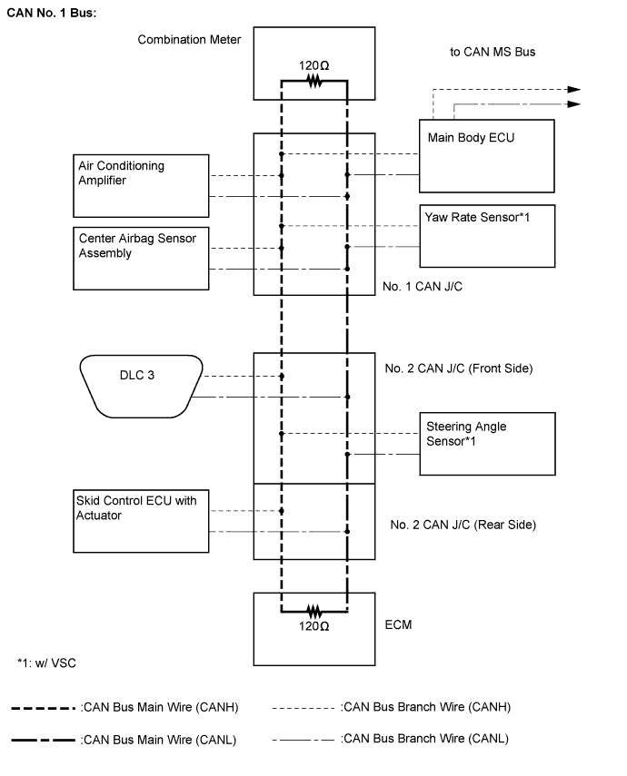
WIRING DIAGRAM
INSPECTION PROCEDURE
CHECK CAN BUS WIRE (MAIN BUS WIRE FOR DISCONNECTION, BUS WIRES FOR SHORT CIRCUIT)
CHECK CAN BUS WIRE (SHORT TO GND IN CAN BUS WIRE)
CHECK CAN BUS WIRE (SHORT TO B+ IN CAN BUS WIRE)
CAN COMMUNICATION SYSTEM (for RHD) - CAN Bus Line |
DESCRIPTION
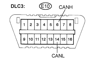
When any DTC of the CAN communication system is output, first measure the resistance between the terminals of the DLC3 to confirm the trouble area.
WIRING DIAGRAM
INSPECTION PROCEDURE
- NOTICE:
- Turn the ignition switch off before measuring the resistance of the CAN main wire and CAN branch wires.
- After the ignition switch is turned off, check that the key reminder warning system and lighting system are not operating.
- Before measuring the resistance, leave the vehicle as is for at least 1 minute and do not operate the ignition switch, any other switches or the doors. If doors need to be opened in order to check connectors, open the doors and leave them open.
- HINT:
- Operating the ignition switch, any other switches or any triggers related ECU and sensor communication on the CAN, which would cause resistance reading variations.
| 1.CHECK CAN BUS WIRE (MAIN BUS WIRE FOR DISCONNECTION, BUS WIRES FOR SHORT CIRCUIT) |
Measure the resistance according to the value(s) in the table below.
- Standard resistance:
Tester Connection
| Condition
| Specified Value
| Result
|
E10-6 (CANH) - E10-14 (CANL)
| Ignition switch off
| 54 to 69 Ω
| OK
|
- Result:
Result
| Proceed to
|
OK
| A
|
70 Ω or higher
| B
|
Below 54 Ω
| C
|
| 2.CHECK CAN BUS WIRE (SHORT TO GND IN CAN BUS WIRE) |
Measure the resistance according to the value(s) in the table below.
- Standard resistance:
Tester Connection
| Condition
| Specified Value
|
E10-4 (CG) - E10-6 (CANH)
| Ignition switch off
| 200 Ω or higher
|
E10-4 (CG) - E10-14 (CANL)
| Ignition switch off
| 200 Ω or higher
|
| 3.CHECK CAN BUS WIRE (SHORT TO B+ IN CAN BUS WIRE) |
Disconnect the cable from the negative (-) battery terminal.
Measure the resistance according to the value(s) in the table below.
- Standard resistance:
Tester Connection
| Condition
| Specified Value
|
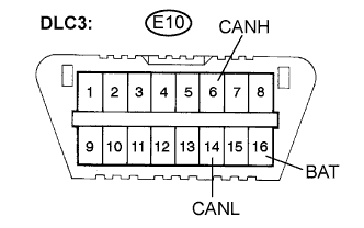
E10-6 (CANH) - E10-16 (BAT)
| Cable disconnected from negative (-) battery terminal
| 6 kΩ or higher
|
E10-14 (CANL) -
E10-16 (BAT)
| Cable disconnected from negative (-) battery terminal
| 6 kΩ or higher
|