Can Communication System (For Rhd) Skid Control Ecu Communication Stop Mode
DESCRIPTION
WIRING DIAGRAM
INSPECTION PROCEDURE
CHECK OPEN IN CAN BUS WIRE (SKID CONTROL ECU BRANCH WIRE)
CHECK WIRE HARNESS (IG1, GND1, GND2)
CAN COMMUNICATION SYSTEM (for RHD) - Skid Control ECU Communication Stop Mode |
DESCRIPTION
Detection Item
| Symptom
| Trouble Area
|
Skid Control ECU Communication Stop Mode
| - "ABS/VSC/TRC" is not displayed on the "Communication Bus Check" screen of the intelligent tester
- Applies to "Skid Control ECU Communication Stop Mode" in the "DTC COMBINATION TABLE"
| - Power source circuit of skid control ECU
- Skid control ECU branch wire or connector
- Skid control ECU
|
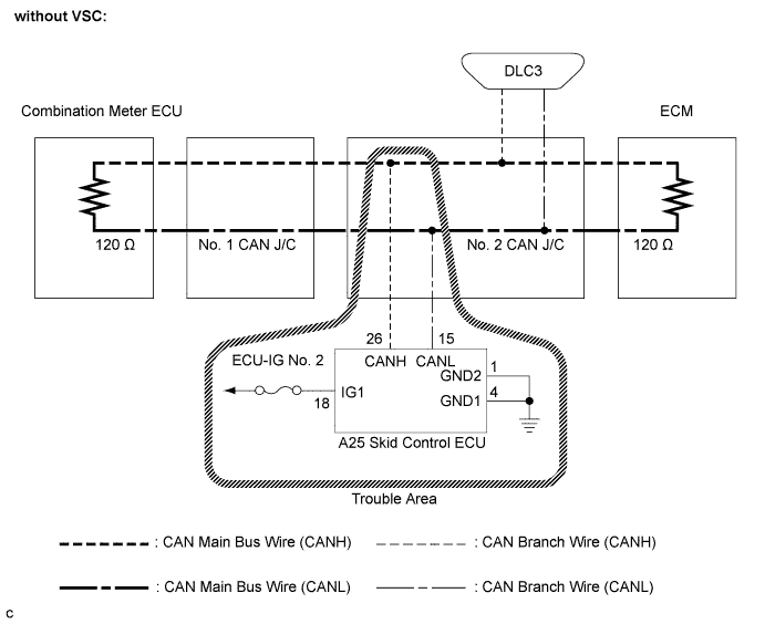
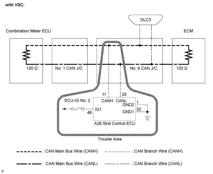
WIRING DIAGRAM
INSPECTION PROCEDURE
- NOTICE:
- Turn the ignition switch off before measuring the resistance of the CAN main wire and CAN branch wires.
- After the ignition switch is turned off, check that the key reminder warning system and lighting system are not operating.
- Before measuring the resistance, leave the vehicle as is for at least 1 minute and do not operate the ignition switch, any other switches or the doors. If doors need to be opened in order to check connectors, open the doors and leave them open.
- HINT:
- Operating the ignition switch, any other switches or any triggers related ECU and sensor communication on the CAN, which would cause resistance reading variations.
| 1.CHECK OPEN IN CAN BUS WIRE (SKID CONTROL ECU BRANCH WIRE) |
Turn the ignition switch off.
Disconnect the skid control ECU connector.
Measure the resistance according to the value(s) in the table below.
- Standard resistance:
- without VSC:
Tester Connection
| Condition
| Specified Value
|
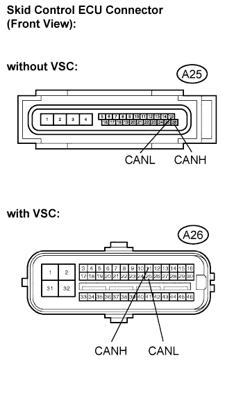
A25-26 (CANH) - A25-15 (CANL)
| Ignition switch off
| 54 to 69 Ω
|
- with VSC:
Tester Connection
| Condition
| Specified Value
|
A26-11 (CANH) - A26-25 (CANL)
| Ignition switch off
| 54 to 69 Ω
|
| | REPAIR OR REPLACE SKID CONTROL ECU BRANCH WIRE OR CONNECTOR (CAN-H, CAN-L) |
|
|
| 2.CHECK WIRE HARNESS (IG1, GND1, GND2) |
Measure the resistance according to the value(s) in the table below.
- Standard resistance:
- without VSC:
Tester Connection
| Condition
| Specified Value
|
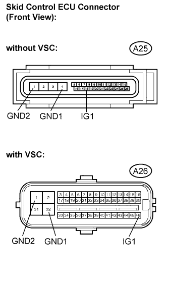
A25-4 (GND1) - Body ground
| Always
| Below 1 Ω
|
A25-1 (GND2) - Body ground
| Always
| Below 1 Ω
|
- with VSC:
Tester Connection
| Condition
| Specified Value
|
A26-32 (GND1) - Body ground
| Always
| Below 1 Ω
|
A26-1 (GND2) - Body ground
| Always
| Below 1 Ω
|
Measure the voltage according to the value(s) in the table below.
- Standard voltage:
- without VSC:
Tester Connection
| Condition
| Specified Value
|
A25-18 (IG1) - Body ground
| Ignition switch on
| 10 to 14 V
|
- with VSC:
Tester Connection
| Condition
| Specified Value
|
A26-46 (IG1) - Body ground
| Ignition switch on
| 10 to 14 V
|
| | REPAIR OR REPLACE HARNESS OR CONNECTOR |
|
|