Dtc B2325 Lin Communication Bus Malfunction
DESCRIPTION
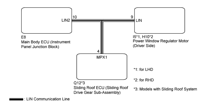
WIRING DIAGRAM
INSPECTION PROCEDURE
CHECK HARNESS AND CONNECTOR (MAIN BODY ECU - EACH ECU)
SYSTEM CHECK
CHECK DTC OUTPUT (SLIDING ROOF ECU (SLIDING ROOF DRIVE GEAR SUB-ASSEMBLY))
CHECK DTC OUTPUT (POWER WINDOW REGULATOR MOTOR (DRIVER SIDE))
CHECK DTC OUTPUT (POWER WINDOW REGULATOR MOTOR (DRIVER SIDE))
REPLACE SLIDING ROOF ECU (SLIDING ROOF DRIVE GEAR SUB-ASSEMBLY)
CHECK DTC OUTPUT
REPLACE POWER WINDOW REGULATOR MOTOR (DRIVER SIDE)
CHECK DTC OUTPUT
DTC B2325 LIN Communication Bus Malfunction |
DESCRIPTION
The main body ECU (Instrument panel junction block) monitors communication between all the ECUs connected to the door system LIN bus lines. When the main body ECU (Instrument panel junction block) detects errors in communication with all the ECUs connected to the door system LIN bus lines at 2.6-second intervals and 3 times in a row, DTC B2325 will be output.DTC No.
| DTC Detection Condition
| Trouble Area
|
B2325
| Main body ECU (Instrument panel junction block) detects errors in communication with the ECUs connected to the door system LIN bus lines 3 times in a row.
| - Sliding roof ECU (Sliding roof drive gear sub-assembly)*
- Power window regulator motor (Driver side)
- Main body ECU (Instrument panel junction block)
- Wire harness or connector
|
- HINT:
- *: Models with Sliding Roof System
WIRING DIAGRAM
INSPECTION PROCEDURE
- NOTICE:
- When using the intelligent tester with the ignition switch off to troubleshoot:
- Connect the intelligent tester to the vehicle, and turn the courtesy switch on and off at 1.5-second intervals until communication between the tester and vehicle begins.
| 1.CHECK HARNESS AND CONNECTOR (MAIN BODY ECU - EACH ECU) |
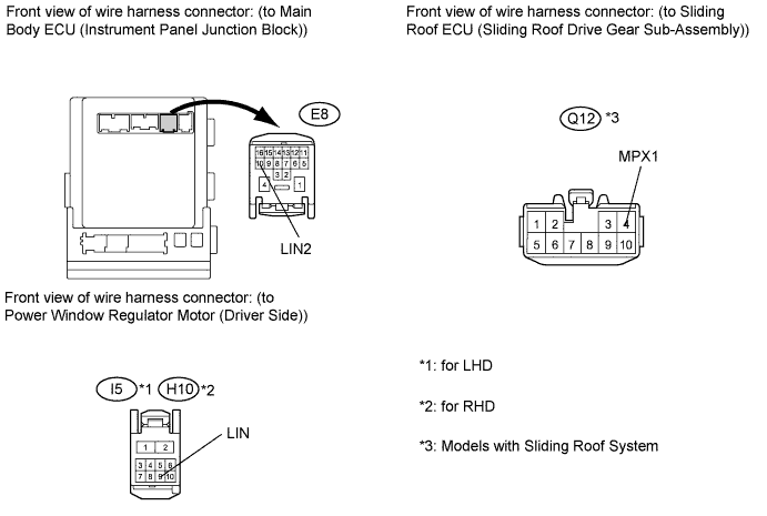
Disconnect the E8 and I5*1 or H10*2 connectors.
- HINT:
- *1: for LHD
- *2: for RHD
Disconnect the Q12*3 connector.
- HINT:
- *3: Models with Sliding Roof System
Measure the resistance according to the value(s) in the table below.
- Standard resistance:
Tester Connection
| Condition
| Specified Condition
|
E8-10 (LIN2) - I5-9 (LIN)*1
E8-10 (LIN2) - H10-9 (LIN)*2
| Always
| Below 1 Ω
|
E8-10 (LIN2) - Q12-4 (MPX1)*3
| Always
| Below 1 Ω
|
E8-10 (LIN2) - Body ground
| Always
| 10 kΩ or higher
|
- HINT:
- *1: for LHD
- *2: for RHD
- *3: Models with Sliding Roof System
Measure the voltage according to the value(s) in the table below.
- Standard voltage:
Tester Connection
| Condition
| Specified Condition
|
E8-10 (LIN2) - Body ground
| Always
| Below 1 V
|
| | REPAIR OR REPLACE HARNESS OR CONNECTOR |
|
|
Check the vehicle specifications.
- Result:
Result
| Proceed to
|
Models with Sliding Roof System
| A
|
Models without Sliding Roof System
| B
|
| 3.CHECK DTC OUTPUT (SLIDING ROOF ECU (SLIDING ROOF DRIVE GEAR SUB-ASSEMBLY)) |
Reconnect the E8 and I5*1 or H10*2 connectors.
- HINT:
- *1: for LHD
- *2: for RHD
Clear the DTC (CAMRY_ACV40 RM000002XHS00KX.html).
Recheck for DTC.
- Result:
Result
| Proceed to
|
B2325 is output
| A
|
B2325 is not output
| B
|
| 4.CHECK DTC OUTPUT (POWER WINDOW REGULATOR MOTOR (DRIVER SIDE)) |
Reconnect the Q12 connector.
Disconnect the I5*1 or H10*2 connector.
- HINT:
- *1: for LHD
- *2: for RHD
Clear the DTC (CAMRY_ACV40 RM000002XHS00KX.html).
Recheck for DTC.
- Result:
Result
| Proceed to
|
B2325 is output
| A
|
B2325 is not output
| B
|
| A |
|
|
|
| REPLACE MAIN BODY ECU (INSTRUMENT PANEL JUNCTION BLOCK) |
|
| 5.CHECK DTC OUTPUT (POWER WINDOW REGULATOR MOTOR (DRIVER SIDE)) |
Reconnect the E8 connector.
Clear the DTC (CAMRY_ACV40 RM000002XHS00KX.html).
Recheck for DTC.
- Result:
Result
| Proceed to
|
B2325 is output
| A
|
B2325 is not output
| B
|
| A |
|
|
|
| REPLACE MAIN BODY ECU (INSTRUMENT PANEL JUNCTION BLOCK) |
|
| 6.REPLACE SLIDING ROOF ECU (SLIDING ROOF DRIVE GEAR SUB-ASSEMBLY) |
Replace the sliding roof ECU (Sliding roof drive gear sub-assembly) (CAMRY_ACV40 RM000001F2C007X.html).
Clear the DTC (CAMRY_ACV40 RM000002XHS00KX.html).
Recheck for DTC.
- Result:
Result
| Proceed to
|
B2325 is not output
| A
|
B2325 is output
| B
|
| | REPLACE MAIN BODY ECU (INSTRUMENT PANEL JUNCTION BLOCK) |
|
|
| A |
|
|
|
| END (SLIDING ROOF ECU IS DEFECTIVE) |
|
| 8.REPLACE POWER WINDOW REGULATOR MOTOR (DRIVER SIDE) |
Replace the power window regulator motor (Driver side) (CAMRY_ACV40 RM000002AC9001X.html).
Clear the DTC (CAMRY_ACV40 RM000002XHS00KX.html).
Recheck for DTC.
- Result:
Result
| Proceed to
|
B2325 is not output
| A
|
B2325 is output
| B
|
| | REPLACE MAIN BODY ECU (INSTRUMENT PANEL JUNCTION BLOCK) |
|
|
| A |
|
|
|
| END (POWER WINDOW REGULATOR MOTOR (DRIVER SIDE) IS DEFECTIVE) |
|