Rear View Monitor System Image From Camera For Rear View Monitor Is Abnormal
DESCRIPTION
WIRING DIAGRAM
INSPECTION PROCEDURE
CONFIRM MODEL
CHECK HARNESS AND CONNECTOR (NAVIGATION RECEIVER - REAR TELEVISION CAMERA)
INSPECT NAVIGATION RECEIVER ASSEMBLY
INSPECT REAR TELEVISION CAMERA ASSEMBLY
CHECK HARNESS AND CONNECTOR (NAVIGATION RECEIVER - LUGGAGE COMPARTMENT DOOR OPENER SWITCH)
INSPECT NAVIGATION RECEIVER ASSEMBLY
INSPECT REAR TELEVISION CAMERA ASSEMBLY
REPLACE LUGGAGE COMPARTMENT DOOR OPENER OUTER SWITCH
CONFIRM SYMPTOMS
REAR VIEW MONITOR SYSTEM - Image from Camera for Rear View Monitor is Abnormal |
DESCRIPTION
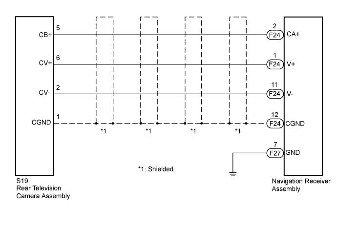
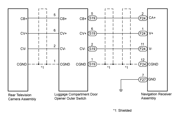
The display signal from the rear television camera assembly transmits to the navigation receiver assembly.
WIRING DIAGRAM
| w/o Entry and Start System |
| w/ Entry and Start System |
INSPECTION PROCEDURE
Chose the model to be inspected.
- Result:
Result
| Proceed to
|
w/o Entry and Start System
| A
|
w/ Entry and Start System
| B
|
| 2.CHECK HARNESS AND CONNECTOR (NAVIGATION RECEIVER - REAR TELEVISION CAMERA) |
Disconnect the F24 connector from the navigation receiver assembly and the S19 connector from the rear television camera assembly.
Measure the resistance according to the value(s) in the table below.
- Standard Resistance:
Tester Connection
| Condition
| Specified Condition
|
S19-6 (CV+) - F24-1 (V+)
| Always
| Below 1 Ω
|
S19-5 (CB+) - F24-2 (CA+)
| Always
| Below 1 Ω
|
S19-1 (CGND) - F24-12 (CGND)
| Always
| Below 1 Ω
|
S19-2 (CV-) - F24-11 (V-)
| Always
| Below 1 Ω
|
S19-6 (CV+) - Body ground
| Always
| 10 kΩ or higher
|
S19-5 (CB+) - Body ground
| Always
| 10 kΩ or higher
|
S19-1 (CGND) - Body ground
| Always
| 10 kΩ or higher
|
S19-2 (CV-) - Body ground
| Always
| 10 kΩ or higher
|
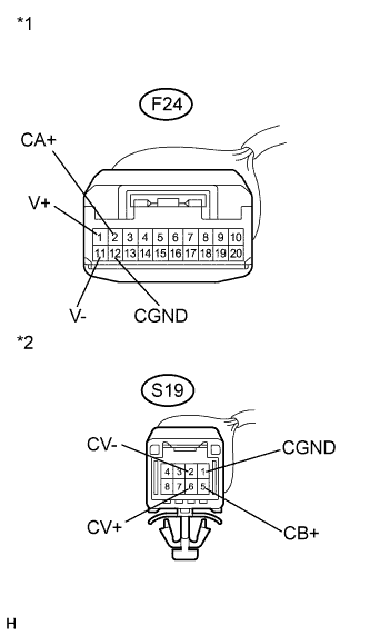
Text in Illustration*1
| Front view of wire harness connector
(to Navigation Receiver Assembly)
|
*2
| Front view of wire harness connector
(to Rear Television Camera Assembly)
|
| | REPAIR OR REPLACE HARNESS OR CONNECTOR (NAVIGATION RECEIVER - REAR TELEVISION CAMERA) |
|
|
| 3.INSPECT NAVIGATION RECEIVER ASSEMBLY |
Reconnect the S19 connector to the rear television camera assembly.
Reconnect the F24 connector to the navigation receiver assembly.
Measure the resistance according to the value(s) in the table below.
- Standard Resistance:
Tester Connection
| Condition
| Specified Condition
|
F24-11 (V-) - Body ground
| Always
| Below 1 Ω
|
F24-12 (CGND) - Body ground
| Always
| Below 1 Ω
|
Measure the voltage according to the value(s) in the table below.
- Standard Voltage:
Tester Connection
| Condition
| Specified Condition
|
F24-2 (CA+) - F24-12 (CGND)
| Ignition switch ON
Shift lever in R
| 5.5 to 7 V
|
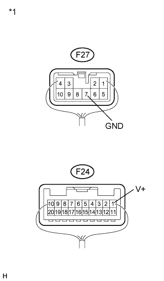
Text in Illustration*1
| Component with harness connected
(Navigation Receiver Assembly)
|
| 4.INSPECT REAR TELEVISION CAMERA ASSEMBLY |
Check that the F27 and F24 connectors are connected to the navigation receiver assembly.
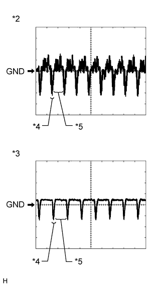
Check the waveform of the rear television camera assembly using an oscilloscope.
- HINT:
- A waterproof connector is used for the rear television camera assembly. Therefore, inspect the waveform at the navigation receiver assembly with the connector connected.
- OK:
- Waveform is as shown in the illustration.
Item
| Content
|
Terminal No. (Symbol)
| F24-1 (V+) - F27-7 (GND)
|
Tool Setting
| 200 mV/DIV., 50 μsec./DIV.
|
Condition
| Ignition switch ON, shift lever in R
|
- HINT:
- The video waveform changes according to the image sent by the rear television camera assembly.
Text in Illustration*1
| Component with harness connected
(to Navigation Receiver Assembly)
|
*2
| Waveform 1 (under normal conditions)
|
*3
| Waveform 2 (camera lens is covered, blacking out the screen)
|
*4
| Synchronized Signal
|
*5
| Video Waveform
|
| 5.CHECK HARNESS AND CONNECTOR (NAVIGATION RECEIVER - LUGGAGE COMPARTMENT DOOR OPENER SWITCH) |
Disconnect the F24 connector from the navigation receiver assembly and the S19 connector from the luggage compartment door opener outer switch.
Measure the resistance according to the value(s) in the table below.
- Standard Resistance:
Tester Connection
| Condition
| Specified Condition
|
S19-6 (CV+) - F24-1 (V+)
| Always
| Below 1 Ω
|
S19-5 (CB+) - F24-2 (CA+)
| Always
| Below 1 Ω
|
S19-1 (CGND) - F24-12 (CGND)
| Always
| Below 1 Ω
|
S19-2 (CV-) - F24-11 (V-)
| Always
| Below 1 Ω
|
S19-6 (CV+) - Body ground
| Always
| 10 kΩ or higher
|
S19-5 (CB+) - Body ground
| Always
| 10 kΩ or higher
|
S19-1 (CGND) - Body ground
| Always
| 10 kΩ or higher
|
S19-2 (CV-) - Body ground
| Always
| 10 kΩ or higher
|
Text in Illustration*1
| Front view of wire harness connector
(to Navigation Receiver Assembly)
|
*2
| Front view of wire harness connector
(to Luggage Compartment Door Opener Outer Switch)
|
| | REPLACE HARNESS OR CONNECTOR (NAVIGATION RECEIVER - LUGGAGE COMPARTMENT DOOR OPENER SWITCH) |
|
|
| 6.INSPECT NAVIGATION RECEIVER ASSEMBLY |
Reconnect the S19 connector to the luggage compartment door opener outer switch.
Reconnect the F24 connector to the navigation receiver assembly.
Measure the resistance according to the value(s) in the table below.
- Standard Resistance:
Tester Connection
| Condition
| Specified Condition
|
F24-11 (V-) - Body ground
| Always
| Below 1 Ω
|
F24-12 (CGND) - Body ground
| Always
| Below 1 Ω
|
Measure the voltage according to the value(s) in the table below.
- Standard Voltage:
Tester Connection
| Condition
| Specified Condition
|
F24-2 (CA+) - F24-12 (CGND)
| Ignition switch ON
Shift lever in R
| 5.5 to 7 V
|
Text in Illustration*1
| Component with harness connected
(Navigation Receiver Assembly)
|
| 7.INSPECT REAR TELEVISION CAMERA ASSEMBLY |
Check that the F27 and F24 connectors are connected to the navigation receiver assembly.
Check the waveform of the rear television camera assembly using an oscilloscope.
- HINT:
- A waterproof connector is used for the rear television camera assembly. Therefore, inspect the waveform at the navigation receiver assembly with the connector connected.
- OK:
- Waveform is as shown in the illustration.
Item
| Content
|
Terminal No. (Symbol)
| F24-1 (V+) - F27-7 (GND)
|
Tool Setting
| 200 mV/DIV., 50 μsec./DIV.
|
Condition
| Ignition switch ON, shift lever in R
|
- HINT:
- The video waveform changes according to the image sent by the rear television camera assembly.
Text in Illustration*1
| Component with harness connected
(to Navigation Receiver Assembly)
|
*2
| Waveform 1 (under normal conditions)
|
*3
| Waveform 2 (camera lens is covered, blacking out the screen)
|
*4
| Synchronized Signal
|
*5
| Video Waveform
|
| 8.REPLACE LUGGAGE COMPARTMENT DOOR OPENER OUTER SWITCH |
Replace the luggage compartment door opener outer switch with a new or normally functioning one (CAMRY_ACV40 RM000001OIW02LX.html).
Check if the same malfunction recurs when the rear view monitor screen is displayed.
- Result:
Result
| Proceed to
|
Malfunction does not reoccur
(returns to normal)
| A
|
Malfunction reoccurs
| B
|