Toyota Parking Assist-Sensor System Speed Signal Circuit
DESCRIPTION
WIRING DIAGRAM
INSPECTION PROCEDURE
CHECK COMBINATION METER ASSEMBLY
CHECK HARNESS AND CONNECTOR (CLEARANCE WARNING ECU - COMBINATION METER ASSEMBLY)
CHECK HARNESS AND CONNECTOR (CLEARANCE WARNING ECU - NO. 3 JUNCTION BLOCK)
TOYOTA PARKING ASSIST-SENSOR SYSTEM - Speed Signal Circuit |
DESCRIPTION
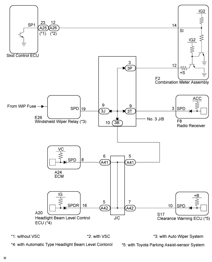
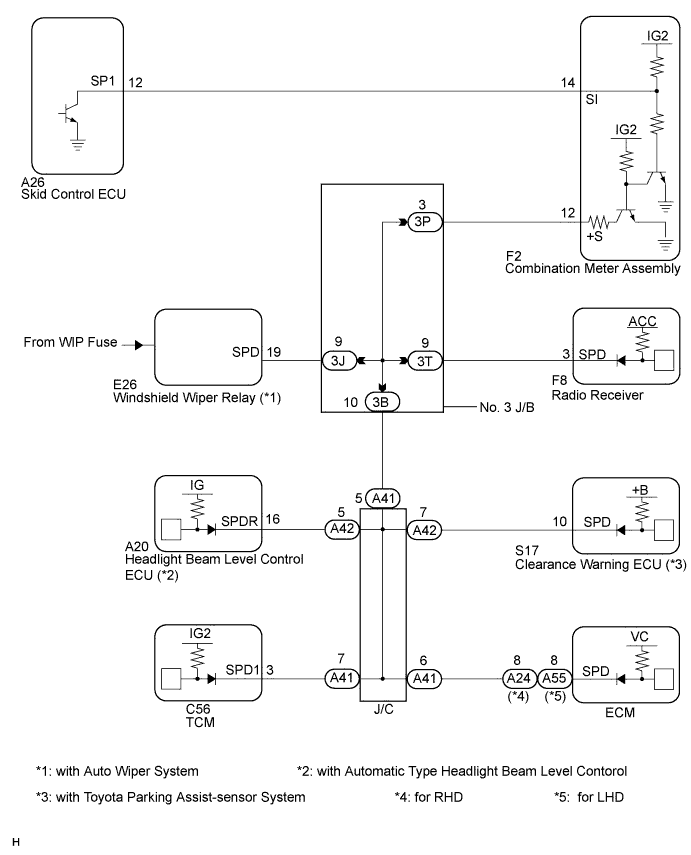
The clearance warning ECU receives the vehicle speed signal from the combination meter assembly.- HINT:
- A voltage of 12 V or 5 V is output from each ECU and then input to the combination meter assembly. The signal is changed to a pulse signal at the transistor in the combination meter assembly. Each ECU controls the respective system based on the pulse signal.
- If a short occurs in any of the ECUs or in the wire harness connected to an ECU, all systems in the diagram below will not operate normally.
WIRING DIAGRAM
INSPECTION PROCEDURE
| 1.CHECK COMBINATION METER ASSEMBLY |
Inspect the circuits that send vehicle speed signals to the combination meter system (CAMRY_ACV40 RM000002UD700ZX.html).
During the inspection, if there is an instruction that indicates to go back to inspections for each system, proceed to the next step.
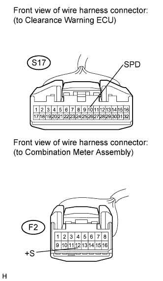
| 2.CHECK HARNESS AND CONNECTOR (CLEARANCE WARNING ECU - COMBINATION METER ASSEMBLY) |
Disconnect the F2 connector from the combination meter assembly and the S17 connector from the clearance warning ECU.
Measure the resistance according to the value(s) in the table below.
- Standard Resistance:
Tester Connection
| Condition
| Specified Condition
|
S17-10 (SPD) - F2-12 (+S)
| Always
| Below 1 Ω
|
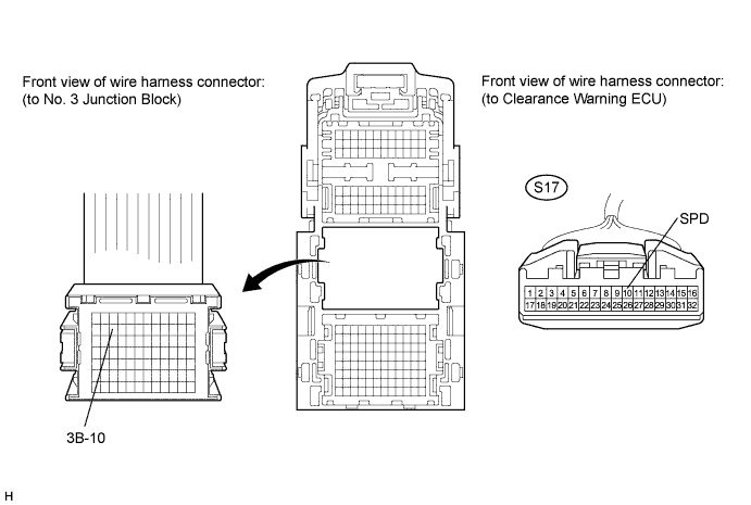
| 3.CHECK HARNESS AND CONNECTOR (CLEARANCE WARNING ECU - NO. 3 JUNCTION BLOCK) |
Disconnect the S17 connector from the clearance warning ECU.
Disconnect the No. 3 junction block connector.
Measure the resistance according to the value(s) in the table below.
- Standard Resistance:
Tester Connection
| Condition
| Specified Condition
|
S17-10 (SPD) - 3B-10
| Always
| Below 1 Ω
|
| | REPAIR OR REPLACE HARNESS OR CONNECTOR |
|
|