Meter / Gauge System System Description
Meter. Camry. Acv40 Gsv40
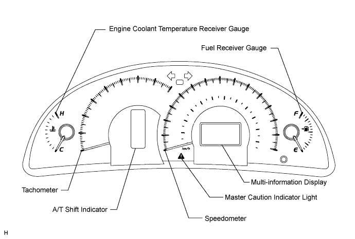
METER GAUGE
MULTI-INFORMATION DISPLAY
DIAGNOSIS SYSTEM
Meter / Gauge System -- System Description |
*: with VSC
METER GAUGE:Item
| Detail
|
Speedometer
| Indicates the vehicle speed receiving a signal from the skid Control ECU. (CAN (CAN No. 1 Bus))
|
Tachometer
| Indicates the engine speed based on a signal received from the ECM. (CAN (CAN No. 1 Bus))
|
Engine Coolant Temperature Receiver Gauge
| Indicates the engine coolant temperature based on a signal received from the ECM. (CAN (CAN No. 1 Bus))
|
Fuel Receiver Gauge
| Indicates the fuel level based on a signal the fuel sender gauge. (Direct Line)
|
WARNING/INDICATORItem
| Detail
|
TURN SIGNAL
| Receives a turn signal from the turn signal flasher. (Direct Line)
|
BEAM
| Receives a beam signal from the main body ECU. (CAN (CAN No. 1 Bus))
|
CHARGE
| Receives a charge light signal from the ECM. (Direct Line)
|
CHECK E/G
| Receives a check engine light signal from the ECM. (Direct Line)
|
DOOR
| Open door indicator light comes on receiving a door condition signal from the main body ECU. (CAN (CAN MS Bus))
|
D-BELT
| Receives a driver side seat belt signal from the center airbag sensor assembly. (CAN (CAN No. 1 Bus))
|
P-BELT
| Receives a passenger side seat belt signal from the front passenger seat belt buckle switch and transmits a passenger side seat belt condition signal to the clock assembly. (Direct Line)
|
TAIL
| Receives a TAIL indicator light signal from the main body ECU. (CAN (CAN No. 1 Bus))
|
A/T SHIFT
| Receives an A/T shift condition and A/T gear position signal from the park/neutral position switch and the ECM. (CAN (CAN No. 1 Bus))
|
FUEL
| Receives a fuel signal from the fuel sender gauge. (Direct Line)
|
ABS
| Receives an ABS signal from the ABS & traction actuator assembly. (CAN (CAN No. 1 Bus))
|
SLIP (*)
| Receives a SLIP signal from the ABS & traction actuator assembly. (CAN (CAN No. 1 Bus))
|
VSC (*)
| Receives a VSC signal from the ABS & traction actuator assembly. (CAN (CAN No. 1 Bus))
|
BRAKE
| Receives a brake signal from the brake fluid level warning switch (Direct Line) and the ABS & traction actuator assembly. (CAN (CAN No. 1 Bus))
|
CRUISE
| Receives a cruise signal from the ECM. (CAN (CAN No. 1 Bus))
|
AIRBAG
| Receives an airbag signal from the center airbag sensor assembly. (CAN (CAN No. 1 Bus))
|
Oil pressure
| Receives an oil pressure signal from the engine oil pressure switch. (Direct Line)
|
Washer
| Receives a washer signal from the washer level switch. (Direct Line)
|
- HINT:
- The multi-information display has been located in the center of the combination meter assembly.
- The display shows a message or animation for each of the functions described in the table below.
MULTI-INFORMATION DISPLAYItem
| Detail
|
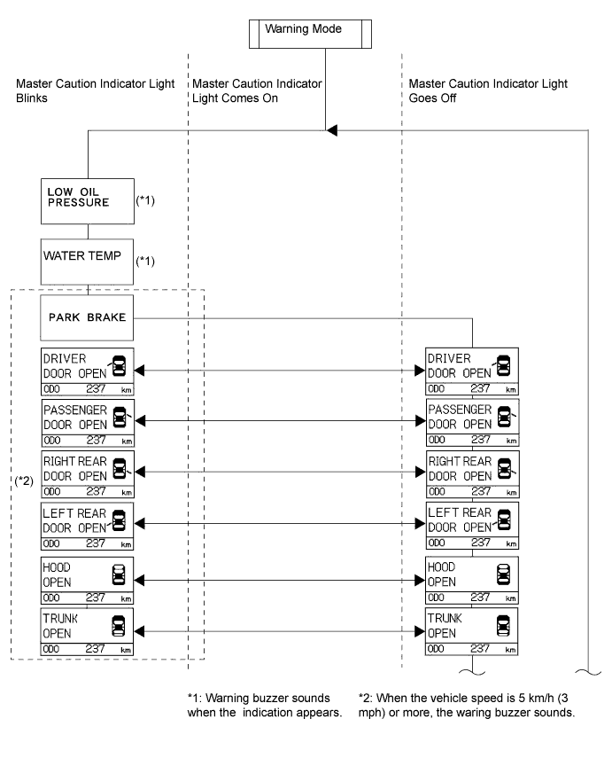
Door warning
| When a door (driver/passenger/rear left/rear right and back) of the vehicle is opened or closed, this item displays a warning message and animation to inform the driver of the condition of the door.
|
ODO/TRIP display
| This display switches between odometer, trip meter A, and trip meter B in accordance with the operation of the ODO/TRIP switch.
|
Outside temperature display
| Displays the outside temperature in accordance with the ambient temperature signal from the A/C control amplifier.
|
Instant fuel consumption
| - Displays the value that has been calculated by the meter CPU, which is based on the driven distance and the fuel consumption volume (fuel injection No.1 injector), provided that turn the ignition switch to the ON position.
- The display updates every 0.5 second.
|
Average fuel consumption
| - Displays the value that has been calculated by the meter CPU, which is based on the driven distance and the fuel consumption volume after the MODE button has been pressed 0.8 second or longer.
- The display updates every 10 seconds.
|
Warning message
| Illuminates or blinks the master warning light and displays a warning message for each type of system failure.
|
DTC (Diagnostic Trouble Code) display (*)
| Displays the DTCs pertaining to the VSC function.
|
| MULTI-INFORMATION DISPLAY |
- HINT:
- The multi-information display shows "DIAG" when turn the ignition switch to the ON position (CAMRY_ACV40 RM000000XHV02RX.html).
- Diagnosis information CAN (CAN No. 1 Bus) be displayed on the multi-information display after connecting a jumper wire between TC and CG of the DLC3 connector.