Power Door Lock Control System Door Control Switch Circuit
DESCRIPTION
WIRING DIAGRAM
INSPECTION PROCEDURE
INSPECT DOOR CONTROL SWITCH ASSEMBLY
CHECK WIRE HARNESS (DOOR CONTROL SWITCH - MAIN BODY ECU (INSTRUMENT PANEL J/B))
POWER DOOR LOCK CONTROL SYSTEM - Door Control Switch Circuit |
DESCRIPTION
When the lock side of the door control switch is pressed, continuity is established between terminal 2 (LHD) or 2 (RHD) and terminal 1 (LHD) or 9 (RHD) of the switch. When the unlock side of the switch is pressed, continuity is established between terminal 9 (LHD), 8 (RHD) and 1 (LHD) or 9 (RHD).Terminals L1 and UL1 of the main body ECU are connected to the door control switch and door lock/unlock request signals (by door control switch operation) are input to the ECU.The main body ECU constantly applies voltage to terminal 2 (LHD) or 2 (RHD) of the door control switch via terminal L1. When the door control switch is operated to lock all doors, current flows from terminal L1 to terminal 2 (LHD) or 2 (RHD). The main body ECU determines that this is door lock request signal input.The main body ECU also applies constant voltage to terminal 9 (LHD) or 2 (RHD) of the door control switch via terminal UL1. When the door control switch is operated to unlock the doors, current flows from terminal UL1 to terminal 9 (LHD) or 2 (RHD). The main body ECU determines that this is door unlock request signal input.
WIRING DIAGRAM
INSPECTION PROCEDURE
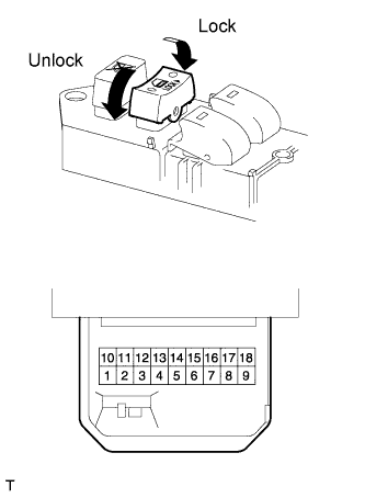
| 1.INSPECT DOOR CONTROL SWITCH ASSEMBLY |
Remove the master switch.
Measure the resistance of the door control switch.
- Standard resistance:
Tester Connection
| Switch Condition
| Specified Condition
|
(*1) 2 - 1
| Lock
| Below 1 Ω
|
(*1) 2 - 1
| OFF (Free)
| 10 kΩ or higher
|
(*1) 9 - 1
| Unlock
| Below 1 Ω
|
(*1) 9 - 1
| OFF (Free)
| 10 kΩ or higher
|
(*2) 2 - 9
| Lock
| Below 1 Ω
|
(*2) 2 - 9
| OFF (Free)
| 10 kΩ or higher
|
(*2) 8 - 9
| Unlock
| Below 1 Ω
|
(*2) 8 - 9
| OFF (Free)
| 10 kΩ or higher
|
*1: LHD
*2: RHD
| | REPLACE DOOR CONTROL SWITCH OR MASTER SWITCH |
|
|
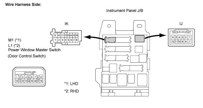
| 2.CHECK WIRE HARNESS (DOOR CONTROL SWITCH - MAIN BODY ECU (INSTRUMENT PANEL J/B)) |
Disconnect the door control switch connector.
Disconnect the ECU (instrument panel J/B) connector.
Measure the resistance according to the value(s) in the table below.
- Standard resistance:
Tester Connection
| Condition
| Specified Condition
|
(*1) M1-2 - IK-15
| Always
| Below 1 Ω
|
(*1) M1-9 - IK-12
| Always
| Below 1 Ω
|
(*1) M1-1 - Body ground
| Always
| Below 1 Ω
|
(*1) IK-15 - Body ground
| Always
| 10 kΩ or higher
|
(*1) IK-12 - Body ground
| Always
| 10 kΩ or higher
|
(*2) L1-2 - IJ-3
| Always
| Below 1 Ω
|
(*2) L1-8 - IJ-4
| Always
| Below 1 Ω
|
(*2) L1-9 - Body ground
| Always
| Below 1 Ω
|
(*2) IJ-3 - Body ground
| Always
| 10 kΩ or higher
|
(*2) IJ-4 - Body ground
| Always
| 10 kΩ or higher
|
*1: LHD
*2: RHD
| | REPAIR OR REPLACE HARNESS OR CONNECTOR |
|
|
| OK |
|
|
|
| PROCEED TO NEXT CIRCUIT INSPECTION SHOWN IN PROBLEM SYMPTOMS TABLE |
|