Lighting System Speed Signal Circuit
DESCRIPTION
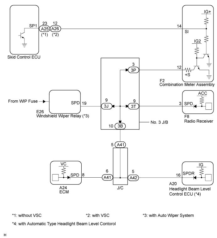
WIRING DIAGRAM
INSPECTION PROCEDURE
CHECK COMBINATION METER SYSTEM
CHECK HARNESS AND CONNECTOR (HEADLIGHT BEAM LEVEL CONTROL ECU - COMBINATION METER)
CHECK HARNESS AND CONNECTOR (HEADLIGHT BEAM LEVEL CONTROL ECU - NO. 3 J/B)
LIGHTING SYSTEM - Speed Signal Circuit |
DESCRIPTION
The headlight beam level control ECU receives the vehicle speed signal from the combination meter.- HINT:
- A voltage of 12 V or 5 V is output from each ECU and then input to the combination meter. The signal is changed to a pulse signal at the transistor in the combination meter. Each ECU controls the respective system based on the pulse signal.
- If a short occurs in any of the ECUs or in the wire harness connected to an ECU, all systems in the diagram below will not operate normally.
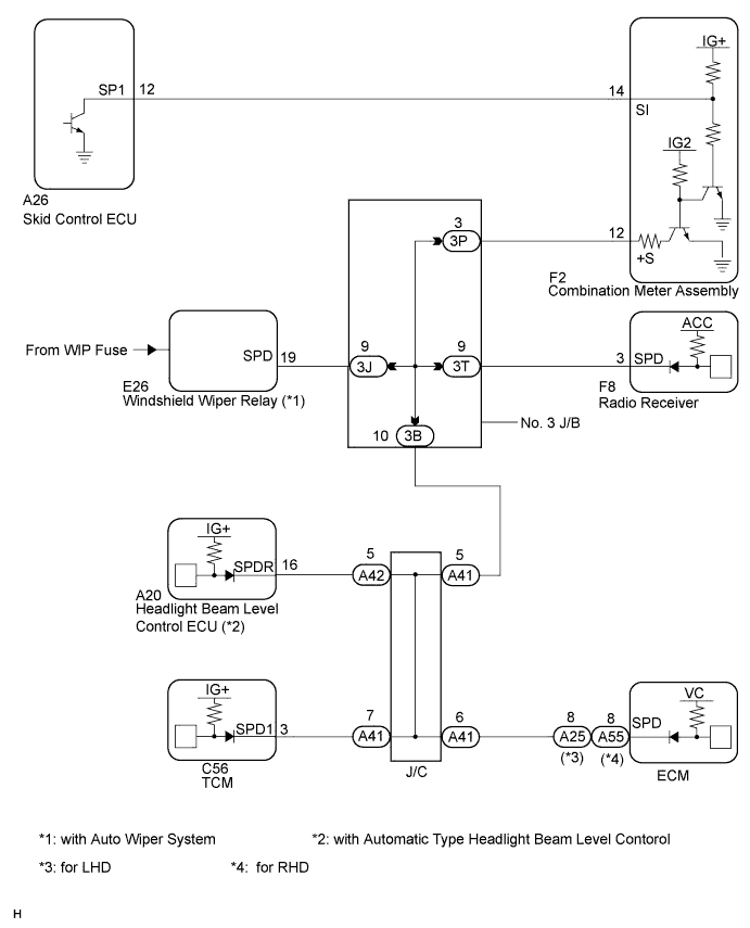
WIRING DIAGRAM
INSPECTION PROCEDURE
| 1.CHECK COMBINATION METER SYSTEM |
The circuits that send vehicle speed signals to this system are inspected in the meter system (CAMRY_ACV40 RM000002UD700KX.html).
During inspection for the meter section, if there is an instruction that indicates to go back inspections for each system, proceed to the next step.
| 2.CHECK HARNESS AND CONNECTOR (HEADLIGHT BEAM LEVEL CONTROL ECU - COMBINATION METER) |
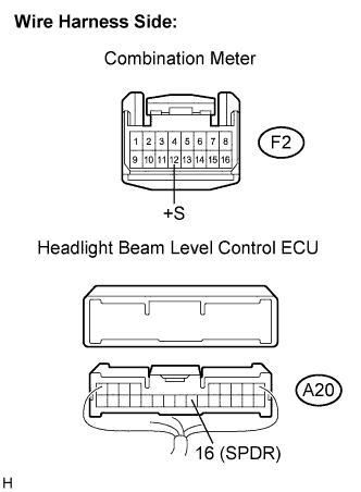
Disconnect the F2 combination meter connector.
Disconnect the A20 headlight beam level control ECU connector.
Measure the resistance according to the value(s) in the table below.
- Standard resistance:
Tester connection
| Condition
| Specified condition
|
A20-16 (SPDR) - F2-12 (+S)
| Always
| Below 1 Ω
|
A20-16 (SPDR) - Body ground
| Always
| 10 kΩ or higher
|
| OK |
|
|
|
| PROCEED TO NEXT CIRCUIT INSPECTION SHOWN IN PROBLEM SYMPTOMS TABLE |
|
| 3.CHECK HARNESS AND CONNECTOR (HEADLIGHT BEAM LEVEL CONTROL ECU - NO. 3 J/B) |
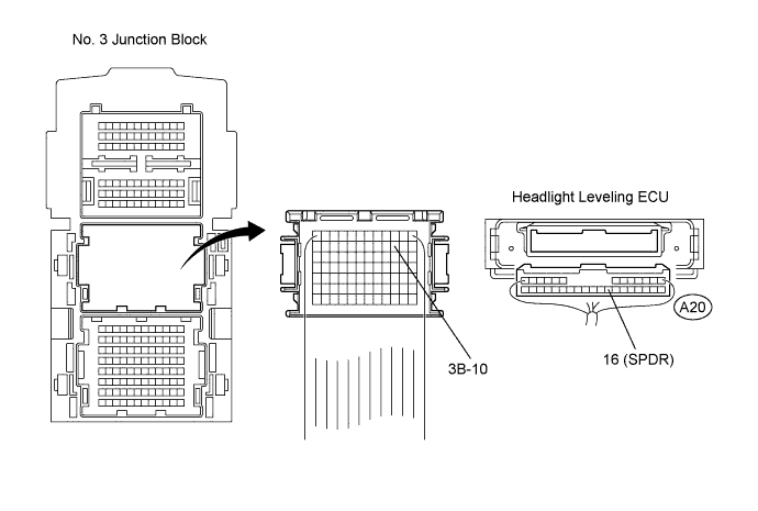
Disconnect the No. 3 J/B connector.
Measure the resistance according to the value(s) in the table below.
- Standard resistance:
Tester Connection
| Condition
| Specified Condition
|
3B-10 - A20-16 (SPDR)
| Always
| Below 1 Ω
|
| | REPAIR OR REPLACE HARNESS OR CONNECTOR (HEADLIGHT BEAM LEVEL CONTROL ECU - NO. 3 J/B) |
|
|
| OK |
|
|
|
| REPAIR OR REPLACE HARNESS OR CONNECTOR (NO. 3 J/B) |
|