Body Electrical. Camry. Acv40 Gsv40
Lighting. Camry. Acv40 Gsv40
CHECK HARNESS AND CONNECTOR (HEADLIGHT LEVELING MOTOR - HEADLIGHT BEAM LEVEL CONTROL ECU)
LIGHTING SYSTEM - Headlight Beam Level Control Actuator Circuit |
DESCRIPTION
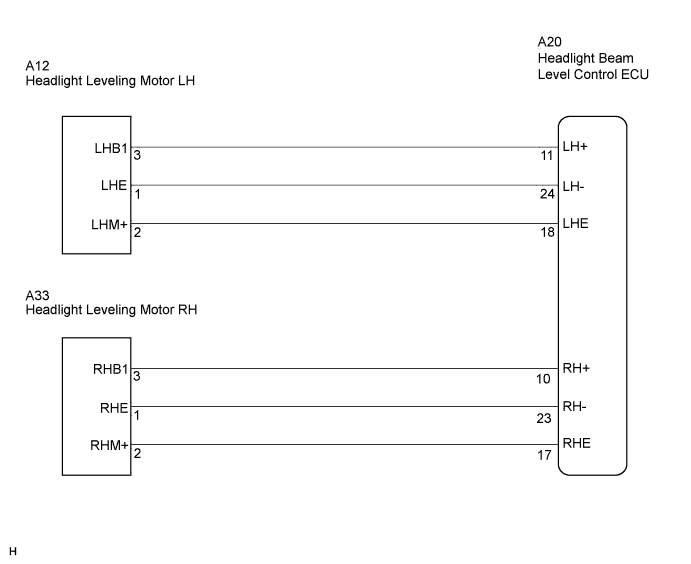
The headlight beam level control ECU actuates the headlight leveling motor according to the vehicle conditions.WIRING DIAGRAM
INSPECTION PROCEDURE
| 1.CHECK HARNESS AND CONNECTOR (HEADLIGHT LEVELING MOTOR - HEADLIGHT BEAM LEVEL CONTROL ECU) |
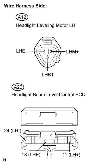
Check the harness and connector between the headlight beam level control ECU and headlight leveling motor LH.
Disconnect the A12 headlight leveling motor LH connector.
Disconnect the A20 headlight beam level control ECU connector.
Measure the resistance according to the value(s) in the table below.
- Standard resistance:
Tester Connection Condition Specified Condition A20-11 (LH+) - A12-3 (LHB1) Always Below 1 Ω A20-24 (LH-) - A12-1 (LHE) Always Below 1 Ω A20-18 (LHE) - A12-2 (LHM+) Always Below 1 Ω A20-11 (LH+) - Body ground Always 10 kΩ or higher A20-24 (LH-) - Body ground Always 10 kΩ or higher A20-18 (LHE) - Body ground Always 10 kΩ or higher
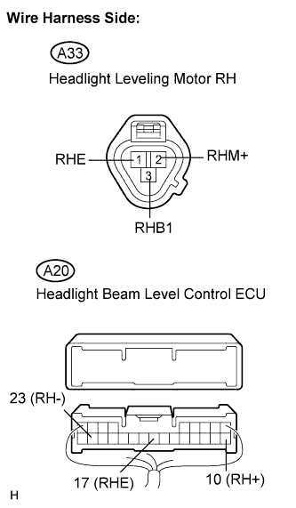
Check the harness and connector between the headlight beam level control ECU and headlight leveling motor RH.
Disconnect the A33 headlight leveling motor RH connector.
Disconnect the A20 headlight beam level control ECU connector.
Measure the resistance according to the value(s) in the table below.
- Standard resistance:
Tester Connection Condition Specified Condition A20-10 (RH+) - A33-3 (RHB1) Always Below 1 Ω A20-23 (RH-) - A33-1 (RHE) Always Below 1 Ω A20-17 (RHE) - A33-2 (RHM+) Always Below 1 Ω A20-10 (RH+) - Body ground Always 10 kΩ or higher A20-23 (RH-) - Body ground Always 10 kΩ or higher A20-17 (RHE) - Body ground Always 10 kΩ or higher
|
| ||||
| OK | ||
| ||