Dtc B2784 Antenna Coil Open / Short
DESCRIPTION
WIRING DIAGRAM
INSPECTION PROCEDURE
READ VALUE USING INTELLIGENT TESTER
CHECK HARNESS AND CONNECTOR (TRANSPONDER KEY ECU - TRANSPONDER KEY AMPLIFIER)
INSPECT TRANSPONDER KEY ECU ASSEMBLY (TRANSPONDER KEY AMPLIFIER POWER SOURCE)
INSPECT TRANSPONDER KEY ECU ASSEMBLY (TRANSPONDER KEY AMPLIFIER GROUND)
DTC B2784 Antenna Coil Open / Short |
DESCRIPTION
The transponder key coil is built into the transponder key amplifier and receives a key code signal from the transponder chip in the key. This signal is amplified by the amplifier, then it is output to the transponder key ECU assembly.DTC No.
| DTC Detection Condition
| Trouble Area
|
B2784
| Antenna coil is open/shorted
| - Wire harness
- Transponder key amplifier
- Transponder key ECU assembly
|
WIRING DIAGRAM
INSPECTION PROCEDURE
- NOTICE:
- If the transponder key ECU assembly is replaced, register the key and ECU communication ID.
| 1.READ VALUE USING INTELLIGENT TESTER |
Connect the intelligent tester to the DLC3.
Turn the ignition switch to the ON position and turn the intelligent tester on.
Select Antenna Coil Status in the DATA LIST and read the value displayed on the intelligent tester.
IMMOBILISER:Tester Display
| Measurement Item/Range
| Normal Condition
| Diagnostic Note
|
Antenna Coil Status
| Transponder key amplifier coil condition/NORMAL or FAIL
| NORMAL: Antenna coil is normal
FAIL: Antenna coil is malfunctioning
| -
|
- OK:
- NORMAL (Antenna coil is normal) appears on the screen.
| | REPLACE TRANSPONDER KEY ECU ASSEMBLY |
|
|
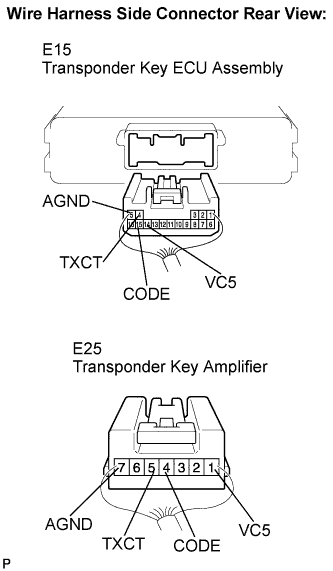
| 2.CHECK HARNESS AND CONNECTOR (TRANSPONDER KEY ECU - TRANSPONDER KEY AMPLIFIER) |
Disconnect the E15 ECU and E25 amplifier connectors.
Measure the resistance according to the value(s) in the table below.
- Standard resistance:
Tester Connection
| Condition
| Specified Condition
|
E15-4 (TXCT) - E25-5 (TXCT)
| Always
| Below 1 Ω
|
E15-5 (AGND) - E25-7 (AGND)
|
E15-14 (VC5) - E25-1 (VC5)
|
E15-15 (CODE) - E25-4 (CODE)
|
E15-4 (TXCT) - Body ground
| 10 kΩ or higher
|
E15-5 (AGND) - Body ground
|
E15-14 (VC5) - Body ground
|
E15-15 (CODE) - Body ground
|
| | REPAIR OR REPLACE HARNESS OR CONNECTOR |
|
|
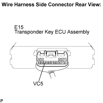
| 3.INSPECT TRANSPONDER KEY ECU ASSEMBLY (TRANSPONDER KEY AMPLIFIER POWER SOURCE) |
Reconnect the E15 ECU and E25 amplifier connectors.
Measure the voltage according to the value(s) in the table below.
- Standard voltage:
Tester Connection
| Condition
| Specified Condition
|
E15-14 (VC5) - Body ground
| No key is in ignition key cylinder
| Below 1 V
|
Key is in ignition key cylinder
| 4.6 to 5.4 V
|
| | REPLACE TRANSPONDER KEY ECU ASSEMBLY |
|
|
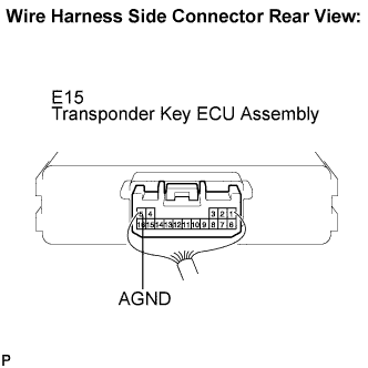
| 4.INSPECT TRANSPONDER KEY ECU ASSEMBLY (TRANSPONDER KEY AMPLIFIER GROUND) |
Measure the resistance according to the value(s) in the table below.
- Standard resistance:
Tester Connection
| Condition
| Specified Condition
|
E15-5 (AGND) - Body ground
| Always
| Below 1 Ω
|
| | REPLACE TRANSPONDER KEY ECU ASSEMBLY |
|
|
| OK |
|
|
|
| REPLACE TRANSPONDER KEY AMPLIFIER |
|