Engine Immobiliser System (W/ Entry And Start System) -- Terminals Of Ecu |
| CHECK ENGINE SWITCH |
Disconnect the E70 engine switch connector.

Measure the resistance according to the value(s) in the table below.
- HINT:
- Measure the values on the wire harness side with the connector disconnected.
If the result is not as specified, there may be a malfunction in the wire harness.Tester Connection Wiring Color Terminal Description Condition Specified Condition E70-8 (AGND) - Body ground G - Body ground Ground Always Below 1 Ω Reconnect the E70 engine switch connector.
Measure the voltage according to the value(s) in the table below.
Tester Connection Wiring Color Terminal Description Condition Specified Condition E70-9 (TXCT) - E70-8 (AGND) GR - G Key code output signal Key not in cabin Below 1 V E70-9 (TXCT) - E70-8 (AGND) GR - G Key code output signal Key held close to engine switch* Pulse generation
(See waveform 1)E70-10 (CODE) - E70-8 (AGND) W - G Demodulated signal of key code data Key not in cabin Below 1 V E70-10 (CODE) - E70-8 (AGND) W - G Demodulated signal of key code data Key held close to engine switch* Pulse generation
(See waveform 2)E70-14 (VC5) - E70-8 (AGND) R - G Power supply Key not in cabin Below 1 V E70-14 (VC5) - E70-8 (AGND) R - G Power supply Brake pedal depressed* 4.6 to 5.4 V - HINT:
- *: Remove the key battery before performing this inspection.
Inspect using an oscilloscope.
Waveform 1 (Reference)
Item Content Tester Connection E70-9 (TXCT) - E70-8 (AGND) Tool Setting 2 V/DIV., 50 ms./DIV. Condition Key is held close to engine switch* - HINT:
- *: Remove the key battery before performing this inspection.
Waveform 2 (Reference)
Item Content Tester Connection E70-10 (CODE) - E70-8 (AGND) Tool Setting 2 V/DIV., 50 ms./DIV. Condition Key is held close to engine switch* - HINT:
- *: Remove the key battery before performing this inspection.
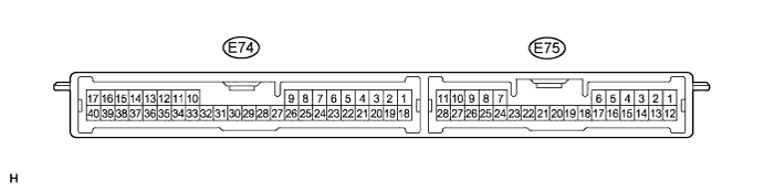
| CHECK CERTIFICATION ECU (SMART KEY ECU ASSEMBLY) |
Disconnect the E74 certification ECU (smart key ECU assembly) connector.
Measure the resistance and voltage according to the value(s) in the table below.
- HINT:
- Measure the values on the wire harness side with the connector disconnected.
If the result is not as specified, there may be a malfunction in the wire harness.Tester Connection Wiring Color Terminal Description Condition Specified Condition E74-1 (+B) - E74-17 (E) W - W-B +B power supply Always 11 to 14 V E74-17 (E) - Body ground W-B - Body ground Ground Always Below 1 Ω Reconnect the E74 certification ECU (smart key ECU assembly) connector.
Measure the resistance and voltage according to the value(s) in the table below.
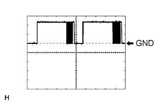
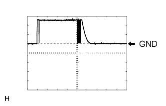
Tester Connection Wiring Color Terminal Description Condition Specified Condition E74-2 (IND) - Body ground Y - Body ground Security indicator light signal Engine switch on (IG), security indicator light off Below 1 V E74-2 (IND) - Body ground Y - Body ground Security indicator light signal Immobiliser set state, security indicator light blinks Repeats 11 to 14 V and below 1 V E74-8 (TXCT) - E74-40 (AGND) GR - G Engine switch TXCT output Key not in cabin Below 1 V E74-8 (TXCT) - E74-40 (AGND) GR - G Engine switch TXCT output Key held close to engine switch* Pulse generation (See waveform 1) E74-9 (CODE) - E74-40 (AGND) W - G Engine switch CODE input Key not in cabin Below 1 V E74-9 (CODE) - E74-40 (AGND) W - G Engine switch CODE input Key held close to engine switch* Pulse generation (See waveform 2) E74-18 (IG) - E74-17 (E) LG - W-B Ignition power supply Engine switch off Below 1 V E74-18 (IG) - E74-17 (E) LG - W-B Ignition power supply Engine switch on (IG) 11 to 14 V E74-19 (ACC) - E74-17 (E) L - W-B ACC power supply Engine switch off Below 1 V E74-19 (ACC) - E74-17 (E) L - W-B ACC power supply Engine switch on (ACC) 11 to 14 V E74-30 (VC5) - E74-40 (AGND) R - G Engine switch power supply Key not in cabin Below 1 V E74-30 (VC5) - E74-40 (AGND) R - G Engine switch power supply Brake pedal depressed* 4.6 to 5.4 V E74-40 (AGND) - Body ground G - Body ground Engine switch ground Always Below 1 Ω - HINT:
- *: Remove the key battery before performing this inspection.
Inspect using an oscilloscope.
Waveform 1 (Reference)
Item Content Tester Connection E74-8 (TXCT) - E74-40 (AGND) Tool Setting 2 V/DIV., 50 ms./DIV. Condition Key is held close to engine switch* - HINT:
- *: Remove the key battery before performing this inspection.
Waveform 2 (Reference)
Item Content Tester Connection E74-9 (CODE) - E74-40 (AGND) Tool Setting 2 V/DIV., 50 ms./DIV. Condition Key is held close to engine switch* - HINT:
- *: Remove the key battery before performing this inspection.
| CHECK ID CODE BOX (IMMOBILISER CODE ECU) |
Disconnect the E68 ID code box (immobiliser code ECU) connector.

Measure the resistance and voltage according to the value(s) in the table below.
- HINT:
- Measure the values on the wire harness side with the connector disconnected.
If the result is not as specified, there may be a malfunction in the wire harness.Tester Connection Wiring Color Terminal Description Condition Specified Condition E68-1 (+B) - E68-8 (GND) W - W-B +B power supply Always 11 to 14 V E68-8 (GND) - Body ground W-B - Body ground Ground Always Below 1 Ω Reconnect the E68 ID code box (immobiliser code ECU) connector.
Measure the voltage according to the value(s) in the table below.
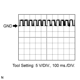
If the result is not as specified, the ID code box (immobiliser code ECU) may have a malfunction.Tester Connection Wiring Color Terminal Description Condition Specified Condition E68-5 (EFII) - E68-8 (GND) G - W-B ECM input signal Engine switch off Below 1 V E68-5 (EFII) - E68-8 (GND) G - W-B ECM input signal Engine switch on (IG) Pulse generation
(See waveform 1)E68-6 (EFIO) - E68-8 (GND) L - W-B ECM output signal Engine switch off Below 1 V E68-6 (EFIO) - E68-8 (GND) L - W-B ECM output signal Engine switch on (IG) Pulse generation
(See waveform 2)Inspect using an oscilloscope.
Waveform 1 (Reference)
Item Content Tester Connection E68-5 (EFII) - E68-8 (GND) Tool Setting 5 V/DIV., 100 ms./DIV. Condition Engine switch on (IG) Waveform 2 (Reference)
Item Content Tester Connection E68-6 (EFIO) - E68-8 (GND) Tool Setting 5 V/DIV., 100 ms./DIV. Condition Engine switch on (IG)

| CHECK STEERING LOCK ECU (STEERING LOCK ACTUATOR ASSEMBLY) |
Disconnect the E69 steering lock ECU (steering lock actuator assembly) connector.

Measure the resistance and voltage according to the value(s) in the table below.
- HINT:
- Measure the values on the wire harness side with the connector disconnected.
If the result is not as specified, there may be a malfunction in the wire harness.Tester Connection Wiring Color Terminal Description Condition Specified Condition E69-1 (GND) - Body ground W-B - Body ground Ground Always Below 1 Ω E69-2 (SGND) - Body ground W-B - Body ground Ground Always Below 1 Ω E69-6 (IG2) - Body ground B - Body ground Ignition power supply Engine switch off Below 1 V E69-6 (IG2) - Body ground P - Body ground Ignition power supply Engine switch on (IG) 11 to 14 V E69-7 (B) - Body ground P - Body ground +B power supply Always 11 to 14 V
| CHECK ECM |
The values listed under "Specified Condition" are reference values. Because waterproof connectors are used for the ECM, inspections can not be performed with the connectors connected.
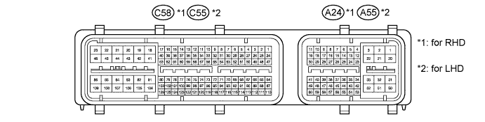
for RHD Tester Connection Wiring Color Terminal Description Condition Specified Condition C58-81 (E1) - Body ground W-B - Body ground Ground Always Below 1 Ω A24-10 (IMO) - C58-81 (E1) G - W-B ID code box (immobiliser code ECU) output signal Engine switch off Below 1 V A24-10 (IMO) - C58-81 (E1) G - W-B ID code box (immobiliser code ECU) output signal Engine switch on (IG) Pulse generation
(See waveform 1)A24-11 (IMI) - C58-81 (E1) Y - W-B ID code box (immobiliser code ECU) input signal Engine switch off Below 1 V A24-11 (IMI) - C58-81 (E1) Y - W-B ID code box (immobiliser code ECU) input signal Engine switch on (IG) Pulse generation
(See waveform 2)for LHD Tester Connection Wiring Color Terminal Description Condition Specified Condition C55-81 (E1) - Body ground W-B - Body ground Ground Always Below 1 Ω A55-10 (IMO) - C55-81 (E1) G - W-B ID code box (immobiliser code ECU) output signal Engine switch off Below 1 V A55-10 (IMO) - C55-81 (E1) G - W-B ID code box (immobiliser code ECU) output signal Engine switch on (IG) Pulse generation
(See waveform 1)A55-11 (IMI) - C55-81 (E1) Y - W-B ID code box (immobiliser code ECU) input signal Engine switch off Below 1 V A55-11 (IMI) - C55-81 (E1) Y - W-B ID code box (immobiliser code ECU) input signal Engine switch on (IG) Pulse generation
(See waveform 2)Waveform:
Waveform 1 (Reference)
Item Content Tester Connection for RHD A24-10 (IMO) - C58-81 (E1) for LHD A55-10 (IMO) - C55-81 (E1) Tool Setting 5 V/DIV., 100 ms./DIV. Condition Engine switch on (IG) Waveform 2 (Reference)
Item Content Tester Connection for RHD A24-11 (IMI) - C58-81 (E1) for LHD A55-11 (IMI) - C55-81 (E1) Tool Setting 5 V/DIV., 100 ms./DIV. Condition Engine switch on (IG)
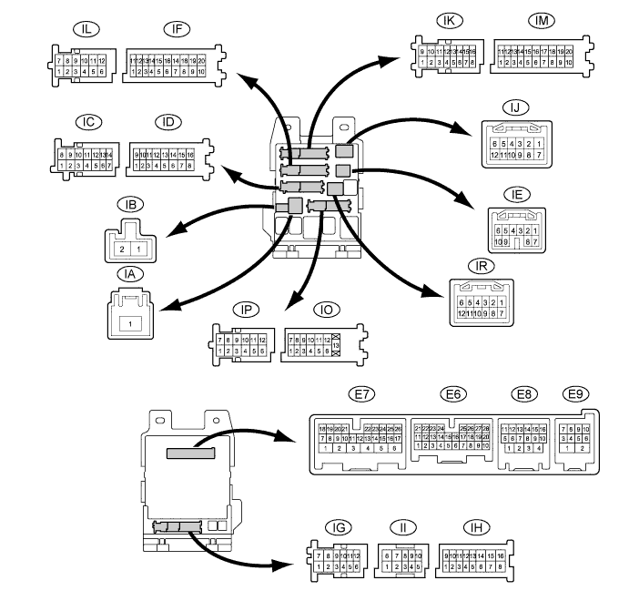
| CHECK MAIN BODY ECU (INSTRUMENT PANEL JUNCTION BLOCK ASSEMBLY) |
Disconnect the ID, IM and IR main body ECU (instrument panel junction block assembly) connectors.
Measure the voltage and resistance according to the value(s) in the table below.
- HINT:
- Measure the values on the wire harness side with the connectors disconnected.
If the result is not as specified, there may be a malfunction in the wire harness.Tester Connection Wiring Color Terminal Description Condition Specified Condition ID-10 (BECU) - Body ground BE - Body ground Battery power supply Always 11 to 14 V ID-16 (ALTB) - Body ground W - Body ground Battery power supply Always 11 to 14 V IM-9 (GND1) - Body ground W-B - Body ground Ground Always Below 1 Ω IR-1 (GND2) - Body ground W-B - Body ground Ground Always Below 1 Ω
| CLOCK ASSEMBLY |
Disconnect the F3 clock assembly connector.

Measure the voltage and resistance according to the value(s) in the table below.
- HINT:
- Measure the values on the wire harness side with the connector disconnected.
If the result is not as specified, there may be a malfunction in the wire harness.Terminal No. (Symbol) Wiring Color Terminal Description Condition Specified Condition F3-1 (B) - Body ground R - Body ground Battery Always 11 to 14 V F3-3 (IG) - Body ground GR - Body ground Engine switch signal Engine switch on (IG) 11 to 14 V F3-3 (IG) - Body ground GR - Body ground Engine switch signal Engine switch off Below 1 V F3-8 (LP) - Body ground Y - Body ground Security indicator light signal Engine switch on (IG), security indicator light off Below 1 V F3-8 (LP) - Body ground Y - Body ground Security indicator light signal Immobiliser set state, security indicator light blinks Repeats 11 to 14 V and below 1 V F3-19 (GND1) - Body ground W-B - Body ground Ground (Signal ground) Always Below 1 Ω