Dtc B1423/23 Pressure Sensor Circuit
DESCRIPTION
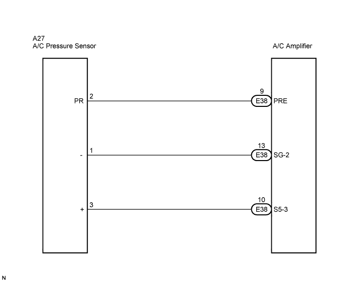
WIRING DIAGRAM
INSPECTION PROCEDURE
CHECK REFRIGERANT PRESSURE
CHECK HARNESS AND CONNECTOR (PRESSURE SENSOR - A/C AMPLIFIER)
INSPECT PRESSURE SENSOR
DTC B1423/23 Pressure Sensor Circuit |
DESCRIPTION
This DTC is output when refrigerant pressure is extremely low (0.19 MPa (2.0 kgf/cm2, 28 psi) or less) or extremely high (3.14 MPa (32.0 kgf/cm2, 455 psi) or more). The pressure sensor, which is installed on the pipe of the high pressure side to detect refrigerant pressure, outputs a refrigerant pressure signal to the A/C amplifier. The A/C amplifier converts this signal to pressure according to the sensor characteristics to control the compressor.- HINT:
- Be sure to check the refrigerant volume first when this DTC is output because this DTC can also be output if there is no refrigerant in the system.
DTC No.
| DTC Detection Condition
| Trouble Area
|
B1423/23
| Open or short in pressure sensor circuit
| - Pressure sensor
- Harness or connector between pressure sensor and A/C amplifier
- Refrigerant pipe line
- A/C amplifier
|
WIRING DIAGRAM
INSPECTION PROCEDURE
| 1.CHECK REFRIGERANT PRESSURE |
Install the manifold gauge set (CAMRY_ACV40 RM000001147007X_01_0002.html).
Read the manifold gauge pressure when the following conditions are established.
Prepare the vehicle according to the chart below.
Item
| Condition
|
Vehicle Doors
| Fully open
|
Temperature Setting
| MAX COLD
|
Blower Speed
| HI
|
A/C Switch
| ON
|
R/F Switch
| RECIRCULATION
(30 to 35°C (86 to 95°F))
|
- Standard pressure:
- Low pressure side:
- 0.15 to 0.25 MPa (1.5 to 2.5 kgf/cm2, 21.3 to 35.6 psi)
- High pressure side:
- 1.37 to 1.57 MPa (14 to 16 kgf/cm2, 199 to 228 psi)
| 2.CHECK HARNESS AND CONNECTOR (PRESSURE SENSOR - A/C AMPLIFIER) |
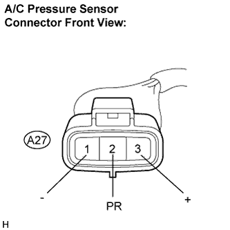
Disconnect the pressure sensor connector.
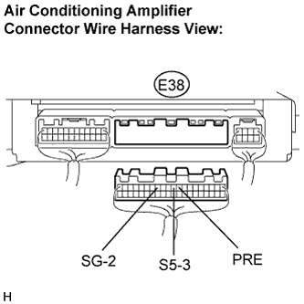
Disconnect the A/C amplifier connector.
Measure the resistance according to the value(s) in the table below.
- Standard resistance:
Tester Connection
| Condition
| Specified Condition
|
A27-2 (PR) - E38-9 (PRE)
| Always
| Below 1 Ω
|
A27-3 (+) - E38-10 (S5-3)
| Always
| Below 1 Ω
|
A27-1 (-) - E38-13 (SG-2)
| Always
| Below 1 Ω
|
E38-9 (PRE) - Body ground
| Always
| 10 kΩ or higher
|
E38-10 (S5-3) - Body ground
| Always
| 10 kΩ or higher
|
E38-13 (SG-2) - Body ground
| Always
| 10 kΩ or higher
|
| | REPAIR OR REPLACE HARNESS OR CONNECTOR |
|
|
| 3.INSPECT PRESSURE SENSOR |
Install the manifold gauge set (CAMRY_ACV40 RM000001147007X_01_0002.html).
Connect the three 1.5 V dry cell batterie's positive (+) lead to terminal 3, and the negative (-) lead to terminal 1. Then connect the voltmeter's positive (+) lead to terminal 2, and the negative (-) lead to terminal 1. Measure the voltage.
- OK:
- The voltage changes according to refrigerant pressure, as shown in the graph.
- Result:
Result
| Proceed to
|
NG
| A
|
OK (When troubleshooting according to the DTC)
| B
|
OK (When troubleshooting according to the PROBLEM SYMPTOMS TABLE)
| C
|
| | REPLACE AIR CONDITIONING AMPLIFIER |
|
|
| | PROCEED TO NEXT CIRCUIT INSPECTION SHOWN IN PROBLEM SYMPTOMS TABLE |
|
|