Dtc C0200/31 Right Front Wheel Speed Sensor Signal Malfunction
Brake. Camry. Acv40 Gsv40
DESCRIPTION
WIRING DIAGRAM
INSPECTION PROCEDURE
READ VALUE USING INTELLIGENT TESTER (FRONT SPEED SENSOR)
PERFORM TEST MODE INSPECTION (SIGNAL CHECK)
INSPECT SPEED SENSOR SIGNAL WAVEFORM
RECONFIRM DTC
INSPECT FRONT SPEED SENSOR INSTALLATION
INSPECT FRONT SPEED SENSOR
CHECK HARNESS AND CONNECTOR (FRONT SPEED SENSOR TO SKID CONTROL ECU)
INSPECT SPEED SENSOR SIGNAL WAVEFORM
READ VALUE USING INTELLIGENT TESTER (FRONT SPEED SENSOR)
RECONFIRM DTC
INSPECT SPEED SENSOR TIP
DTC C0200/31 Right Front Wheel Speed Sensor Signal Malfunction |
DTC C0205/32 Left Front Wheel Speed Sensor Signal Malfunction |
DTC C1271/71 Low Output Signal of Front Speed Sensor RH (Test Mode DTC) |
DTC C1272/72 Low Output Signal of Front Speed Sensor LH (Test Mode DTC) |
DTC C1275/75 Abnormal Change in Output Signal of Front Speed Sensor RH (Test Mode DTC) |
DTC C1276/76 Abnormal Change in Output Signal of Front Speed Sensor LH (Test Mode DTC) |
DTC C1330/35 Right Front Speed Sensor Circuit |
DTC C1331/36 Left Front Speed Sensor Circuit |
DESCRIPTION
The speed sensors detect wheel speed and transmit the signals to the skid control ECU. These signals are used for control of the ABS control system. Each of the front and rear rotors has 48 serrations.When the rotors rotate, the magnetic field generated by the permanent magnet in the speed sensor induces AC voltage. Since the frequency of this AC voltage changes in direct proportion to the speed of the rotor, the frequency is used by the ECU to detect the speed of each wheel.DTCs C1271/71 to C1276/76 can be deleted when the speed sensor sends a wheel speed signal or the test mode ends. DTCs C1271/71 to C1276/76 are output only in the test mode.
DTC No.
| DTC Detecting Condition
| Trouble Area
|
C0200/31
C0205/32
| When either of the following is detected:
- Vehicle speed is more than 40 km/h (25 mph), and pulses are not input for 0.03 sec.
- When the vehicle speed has reached 12 km/h (8 mph) after the initial start or restart, a wheel speed of 0 km/h (0 mph) is detected.
| - Front speed sensor RH and/or LH
- Front speed sensor circuit RH and/or LH
- Front speed sensor rotor RH and/or LH
- Sensor installation
- Brake actuator assembly (skid control ECU)
|
C1330/35
C1331/36
| Abnormality in the resistance value of each speed sensor is detected.
| - Front speed sensor RH and/or LH
- Front speed sensor circuit RH and/or LH
- Sensor installation
|
C1271/71
C1272/72
| Detected only during test mode.
| - Front speed sensor
- Sensor installation
- Sensor rotor
|
C1275/75
C1276/76
| Detected only during test mode.
| - Front speed sensor
- Front speed sensor circuit
- Sensor installation
|
- HINT:
- DTC No. C0200/31 and C1330/35 are for the front speed sensor RH.
- DTC No. C0205/32 and C1331/36 are for the front speed sensor LH.
WIRING DIAGRAM
INSPECTION PROCEDURE
- HINT:
- Check the condition of each related circuit connector before troubleshooting (CAMRY_ACV40 RM000000UZ301ZX.html).
| 1.READ VALUE USING INTELLIGENT TESTER (FRONT SPEED SENSOR) |
Connect the intelligent tester to the DLC3.
Start the engine.
Select "Data List" and read the value displayed on the intelligent tester (CAMRY_ACV40 RM000001JBA003X.html).
Data List: ABSTester Display
| Measurement Item/Range
| Normal Condition
|
FR Wheel Speed
| Wheel speed sensor (FR) reading / min.: 0 km/h (0 mph), max.: 326 km/h (202 mph)
| Actual wheel speed
|
FL Wheel Speed
| Wheel speed sensor (FL) reading / min.: 0 km/h (0 mph), max.: 326 km/h (202 mph)
| Actual wheel speed
|
Check that there is no difference between the speed value output from the speed sensor displayed on the intelligent tester and the speed value displayed on the speedometer when driving the vehicle.
- OK:
- The speed value output from the speed sensor displayed on the intelligent tester is the same as the actual vehicle speed.
| 2.PERFORM TEST MODE INSPECTION (SIGNAL CHECK) |
Check if test mode (signal check) DTCs are detected (CAMRY_ACV40 RM000001JBD011X.html).
- Result:
Condition
| Proceed to
|
Test mode (signal check) DTC is not output
| A
|
Test mode (signal check) DTC is output
| B
|
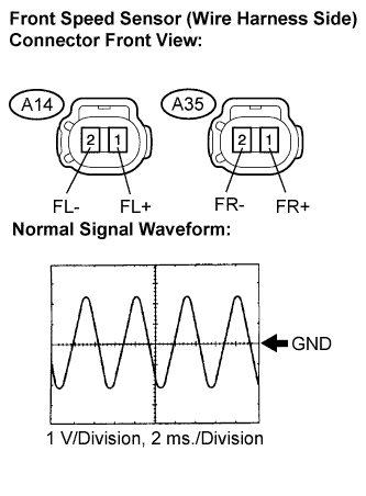
| 3.INSPECT SPEED SENSOR SIGNAL WAVEFORM |
Lift up the vehicle.
Perform the inspection using an oscilloscope.
Disconnect the front speed sensor connector.
Connect the oscilloscope to terminals 1 and 2 of the front speed sensor.
Check that a waveform is output when the tires are rotated.
- OK:
- The same waveform is output from front wheels and there is no noise or interference in the waveform.
- HINT:
- As vehicle speed (wheel rotation speed) increases, the width of the waveform narrows and the output voltage becomes greater.
- When noise is identified in the waveform on the oscilloscope, the erratic signals are generated due to rotor scratches, looseness or foreign matter attached to the speed sensor.
Connect the connector.
Clear the DTCs (CAMRY_ACV40 RM000001JB800HX.html).
Drive the vehicle at a speed of approximately 40 km/h (25 mph) or more for 60 seconds or more.
Check if the same DTCs are recorded (CAMRY_ACV40 RM000001JB800HX.html).
- HINT:
- Reinstall the sensors, connectors, etc. and restore the vehicle to its prior condition before rechecking for DTCs.
- Result:
Condition
| Proceed to
|
DTCs (C0200/31, C0205/32, C1330/35 and C1331/36) are output
| A
|
DTCs (C0200/31, C0205/32, C1330/35 and C1331/36) are output (When troubleshooting in accordance with the PROBLEM SYMPTOMS TABLE)
| B
|
DTCs (C0200/31, C0205/32, C1330/35 and C1331/36) are not output (When troubleshooting in accordance with the DTC CHART)
| C
|
| 5.INSPECT FRONT SPEED SENSOR INSTALLATION |
Check the front speed sensor installation.
- OK:
- The installation bolt is tightened properly.
There is no clearance between the sensor and front steering knuckle.
- Torque:
- 8.0 N*m{82 kgf*cm, 71 in.*lbf}
- NOTICE:
- Check the speed sensor signal after replacement (CAMRY_ACV40 RM000001JBD011X.html).
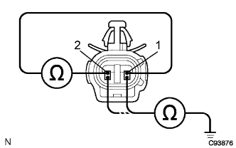
| 6.INSPECT FRONT SPEED SENSOR |
Make sure that there is no looseness at the locking part and the connecting part of the connectors.
Disconnect the front speed sensor connectors.
Measure the resistance according to the value(s) in the table below.
- Standard resistance:
- LH:
Tester Connection
| Specified Condition
|
A14-1 (FL+) - A14-2 (FL-)
| 1.4 to 1.8 kΩ at 20°C (68°F)
|
A14-1 (FL+) - Body ground
| 10 kΩ or higher
|
A14-2 (FL-) - Body ground
| 10 kΩ or higher
|
- RH:
Tester Connection
| Specified Condition
|
A35-1 (FR+) - A35-2 (FR-)
| 1.4 to 1.8 kΩ at 20°C(68°F)
|
A35-1 (FR+) - Body ground
| 10 kΩ or higher
|
A35-2 (FR-) - Body ground
| 10 kΩ or higher
|
- NOTICE:
- Check the speed sensor signal after replacement (CAMRY_ACV40 RM000001JBD011X.html).
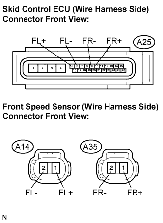
| 7.CHECK HARNESS AND CONNECTOR (FRONT SPEED SENSOR TO SKID CONTROL ECU) |
Disconnect the skid control ECU connector.
Measure the resistance according to the value(s) in the table below.
- Standard resistance:
- LH:
Tester Connection
| Specified Condition
|
A25-5 (FL+) - A14-1 (FL+)
| Below 1 Ω
|
A25-6 (FL-) - A14-2 (FL-)
| Below 1 Ω
|
A14-1 (FL+) - Body ground
| 10 kΩ or higher
|
A14-2 (FL-) - Body ground
| 10 kΩ or higher
|
- RH:
Tester Connection
| Specified Condition
|
A25-10 (FR+) - A35-1 (FR+)
| Below 1 Ω
|
A25-9 (FR-) - A35-2 (FR-)
| Below 1 Ω
|
A35-1 (FR+) - Body ground
| 10 kΩ or higher
|
A35-2 (FR-) - Body ground
| 10 kΩ or higher
|
Connect the connectors.
| | REPAIR OR REPLACE HARNESS OR CONNECTOR (FRONT SPEED SENSOR TO SKID CONTROL ECU) |
|
|
| 8.INSPECT SPEED SENSOR SIGNAL WAVEFORM |
Lift up the vehicle.
Perform the inspection using an oscilloscope.
Disconnect the front speed sensor connector.
Connect the oscilloscope to terminals 1 and 2 of the front speed sensor.
Check that a waveform is output when the tires are rotated.
- OK:
- The same waveforms is output from front wheels and there is no noise or interference in the waveform.
- HINT:
- As vehicle speed (wheel rotation speed) increases, the width of the waveform narrows and the output voltage becomes greater.
- When noise is identified in the waveform on the oscilloscope, the erratic signals are generated due to rotor scratches, looseness or foreign matter attached to the speed sensor.
Connect the connector.
| 9.READ VALUE USING INTELLIGENT TESTER (FRONT SPEED SENSOR) |
Connect the intelligent tester to the DLC3.
Start the engine.
Select "Data List" and read the value displayed on the intelligent tester (CAMRY_ACV40 RM000001JBA003X.html).
Data List: ABSTester Display
| Measurement Item/Range
| Normal Condition
|
FR Wheel Speed
| Wheel speed sensor (FR) reading / min.: 0 km/h (0 mph), max.: 326 km/h (202 mph)
| Actual wheel speed
|
FL Wheel Speed
| Wheel speed sensor (FL) reading / min.: 0 km/h (0 mph), max.: 326 km/h (202 mph)
| Actual wheel speed
|
Check that there is no difference between the speed value output from the speed sensor displayed on the intelligent tester and the speed value displayed on the speedometer when driving the vehicle.
- OK:
- The speed value output from the speed sensor displayed on the intelligent tester is the same as the actual vehicle speed.
- HINT:
- If troubleshooting has been carried out according to the "PROBLEM SYMPTOMS TABLE", refer back to the table and proceed to the next step before replacing the part (CAMRY_ACV40 RM000001JB500GX.html).
Clear the DTCs (CAMRY_ACV40 RM000001JB800HX.html).
Drive the vehicle at a speed of approximately 40 km/h (25 mph) or more for 60 seconds or more.
Check if the same DTCs are recorded (CAMRY_ACV40 RM000001JB800HX.html).
- HINT:
- Reinstall the sensors, connectors, etc. and restore the vehicle to its prior condition before rechecking for DTCs.
- Result:
Condition
| Proceed to
|
DTCs (C0200/31, C0205/32, C1330/35 and C1331/36) are output
| A
|
DTCs (C0200/31, C0205/32, C1330/35 and C1331/36) are not output
| B
|
| 11.INSPECT SPEED SENSOR TIP |
Remove the front speed sensor (CAMRY_ACV40 RM0000011P500NX.html).
Check the sensor tip.
- OK:
- No scratches or foreign matter on the sensor tip.
- NOTICE:
- Check the speed sensor signal after cleaning or replacement (CAMRY_ACV40 RM000001JBD011X.html).
Install the speed sensor.
| | CLEAN OR REPLACE SPEED SENSOR |
|
|
| OK |
|
|
|
| CLEAN OR REPLACE SPEED SENSOR ROTOR |
|