Front Drive Shaft Removal
DRAIN AUTOMATIC TRANSAXLE FLUID (for Automatic Transaxle)
DRAIN MANUAL TRANSAXLE OIL (for Manual Transaxle)
REMOVE FRONT WHEEL
REMOVE FRONT AXLE HUB NUT
SEPARATE FRONT STABILIZER LINK ASSEMBLY
SEPARATE FRONT SPEED SENSOR
SEPARATE TIE ROD END SUB-ASSEMBLY
SEPARATE FRONT SUSPENSION LOWER NO. 1 ARM
SEPARATE FRONT AXLE ASSEMBLY
REMOVE FRONT DRIVE SHAFT ASSEMBLY LH
REMOVE FRONT DRIVE SHAFT ASSEMBLY RH
SECURE FRONT AXLE HUB SUB-ASSEMBLY
INSPECT FRONT DRIVE SHAFT ASSEMBLY
Front Drive Shaft -- Removal |
- HINT:
- Use the same procedures for the RH side and LH side.
- The procedures listed below are for the LH side.
| 1. DRAIN AUTOMATIC TRANSAXLE FLUID (for Automatic Transaxle) |
for 2GR-FE: CAMRY_ACV40 RM0000016DV01FX_02_0488.html
for 2AZ-FE: CAMRY_ACV40 RM000000YWV02CX_01_0026.html
| 2. DRAIN MANUAL TRANSAXLE OIL (for Manual Transaxle) |
Remove the filler plug and the gasket.
Remove the drain plug and gasket, and drain the manual transaxle oil.
Install a new gasket and the drain plug.
- Torque:
- 49 N*m{500 kgf*cm, 36 ft.*lbf}
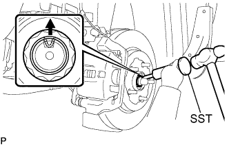
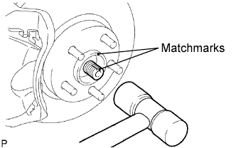
| 4. REMOVE FRONT AXLE HUB NUT |
Using SST and a hammer, release the staked part of the front axle hub nut.
- SST
- 09930-00010
- NOTICE:
- Loosen the staked part of the nut completely, otherwise the thread of the drive shaft may be damaged.
While applying the brakes, remove the front axle hub nut.
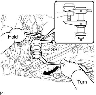
| 5. SEPARATE FRONT STABILIZER LINK ASSEMBLY |
Remove the nut and separate the front stabilizer link assembly.
- HINT:
- If the ball joint turns together with the nut, use a hexagon wrench (6 mm) to hold the stud.
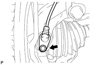
| 6. SEPARATE FRONT SPEED SENSOR |
Remove the bolt and clip, and separate the speed sensor wire and flexible hose from the shock absorber.
Remove the bolt and separate the speed sensor from the steering knuckle.
- NOTICE:
- Prevent foreign matter from adhering to the speed sensor.
- Be careful not to damage the speed sensor.
| 7. SEPARATE TIE ROD END SUB-ASSEMBLY |
Remove the cotter pin and nut.
Using SST, separate the tie rod end sub-assembly from the steering knuckle.
- SST
- 09628-00011
- NOTICE:
- Make sure that the string of the SST is securely tied to the vehicle.
- Be careful not to damage the ball joint dust cover.
- Be careful not to damage the steering knuckle.
- Be careful not to damage the front disc brake dust cover.
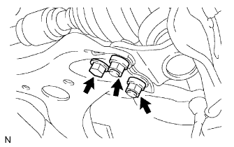
| 8. SEPARATE FRONT SUSPENSION LOWER NO. 1 ARM |
Remove the bolt and 2 nuts, and separate the front suspension lower No. 1 arm from the lower ball joint.
| 9. SEPARATE FRONT AXLE ASSEMBLY |
Put matchmarks on the front drive shaft assembly and the axle hub.
Using a plastic hammer, separate the front drive shaft assembly from the front axle assembly.
- NOTICE:
- Be careful not to damage the drive shaft boot and speed sensor rotor.
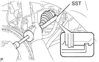
| 10. REMOVE FRONT DRIVE SHAFT ASSEMBLY LH |
Using SST, remove the front drive shaft assembly LH.
- SST
- 09520-01010
09520-24010(09520-32040)
- NOTICE:
- Be careful not to damage the drive shaft dust cover, boot, and oil seal.
- Be careful not to drop the drive shaft assembly.
| 11. REMOVE FRONT DRIVE SHAFT ASSEMBLY RH |
Using a screwdriver, remove the bearing bracket hole snap ring.
Remove the bolt and front drive shaft assembly RH from the drive shaft bearing bracket.
- NOTICE:
- Do not damage the boot and oil seal.
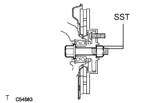
| 12. SECURE FRONT AXLE HUB SUB-ASSEMBLY |
Secure the front axle hub bearing.
- SST
- 09608-16042(09608-02021,09608-02041)
- NOTICE:
- The hub bearing may be damaged if it is subjected to the vehicle's full weight, such as moving the vehicle with the drive shaft removed. If it is necessary to place the vehicle's weight on the hub bearing, first support it with SST.
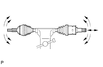
| 13. INSPECT FRONT DRIVE SHAFT ASSEMBLY |
Check that there is no excessive play in the outboard joint.
Check that the inboard joint slides smoothly in the thrust direction.
Check that there is no excessive play in the radial directions of the inboard joint.
Check the boots for damage.