Automatic Transaxle Unit Inspection
INSPECT TRANSMISSION OIL CLEANER MAGNET
INSPECT INPUT SHAFT SUB-ASSEMBLY
INSPECT NO. 2 CLUTCH DISC
INSPECT PLANETARY SUN GEAR SUB-ASSEMBLY
INSPECT NO. 1 CLUTCH DISC
INSPECT NO. 3 BRAKE DISC
INSPECT UNDERDRIVE PLANETARY GEAR ASSEMBLY
INSPECT REAR PLANETARY SUN GEAR ASSEMBLY
INSPECT NO. 1 BRAKE DISC
INSPECT 2ND BRAKE PISTON RETURN SPRING SUB-ASSEMBLY
INSPECT ONE-WAY CLUTCH ASSEMBLY
INSPECT PLANETARY GEAR ASSEMBLY
INSPECT NO. 2 BRAKE DISC
INSPECT 1ST AND REVERSE BRAKE RETURN SPRING SUB-ASSEMBLY
INSPECT CLEARANCE OF NO. 2 BRAKE
INSPECT CLEARANCE OF NO. 1 BRAKE
INSPECT CLEARANCE OF NO. 3 BRAKE
INSPECT CLEARANCE OF NO. 1 CLUTCH DISC
INSPECT CLEARANCE OF NO. 2 CLUTCH DISC
Automatic Transaxle Unit -- Inspection |
| 1. INSPECT TRANSMISSION OIL CLEANER MAGNET |
Use the removed magnets to collect any steel chips. Examine the chips and particles in the pan and on the magnets to determine what type of wear has occurred in the transaxle:
- Result:
- Steel (magnetic):
- Bearing, gear and plate wear
- Brass (non-magnetic):
- Bearing wear
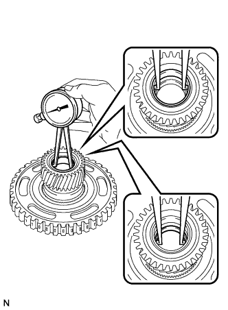
| 2. INSPECT INPUT SHAFT SUB-ASSEMBLY |
Using a dial indicator, measure the input shaft end play.
- End play:
- 0.012 to 1.250 mm (0.0005 to 0.0492 in.)
| 3. INSPECT NO. 2 CLUTCH DISC |
Check if the sliding surfaces of the discs, plates, and flange are worn or burnt. If necessary, replace them.
- NOTICE:
- If the linings of the discs are peeled off or discolored, or even if a part of the groove is damaged, replace all discs.
| 4. INSPECT PLANETARY SUN GEAR SUB-ASSEMBLY |
Using a dial indicator, measure the inside diameter of the bushings of the planetary sun gear.
- Standard inside diameter:
- 25.525 to 25.546 mm (1.0049 to 1.0057 in.)
- Maximum inside diameter:
- 25.546 mm (1.0057 in.)
If the inside diameter is greater than the maximum, replace the planetary gear sun gear.
| 5. INSPECT NO. 1 CLUTCH DISC |
Check if the sliding surfaces of the discs, plates, and flange are worn or burnt. If necessary, replace them.
- NOTICE:
- If the linings of the discs are peeled off or discolored, or even if a part of the groove is damaged, replace all discs.
| 6. INSPECT NO. 3 BRAKE DISC |
Check if the sliding surfaces of the discs, plates, and flange are worn or burnt. If necessary, replace them.
- NOTICE:
- If the linings of the discs are peeled off or discolored, or even if a part of the groove is damaged, replace all discs.
| 7. INSPECT UNDERDRIVE PLANETARY GEAR ASSEMBLY |
Using a feeler gauge, measure the clearance between the underdrive planetary gear and the pinion gear at 4 points.
- Standard clearance:
- 0.18 to 0.54 mm (0.0071 to 0.0213 in.)
If the clearance is greater than the standard clearance, replace the underdrive planetary gear sun gear.
| 8. INSPECT REAR PLANETARY SUN GEAR ASSEMBLY |
Using a dial indicator, measure the inside diameter of the bushing of the rear planetary sun gear sub-assembly.
- Standard inside diameter:
- 25.580 to 25.601 mm (1.0071 to 1.0079 in.)
- Maximum inside diameter:
- 25.601 mm (1.0079 in.)
If the inside diameter is greater than the maximum, replace the rear planetary sun gear sub-assembly.
| 9. INSPECT NO. 1 BRAKE DISC |
Check if the sliding surfaces of the discs, plates, and flange are worn or burnt. If necessary, replace them.
- NOTICE:
- If the linings of the discs are peeled off or discolored, or even if a part of the groove is damaged, replace all discs.
| 10. INSPECT 2ND BRAKE PISTON RETURN SPRING SUB-ASSEMBLY |
Using vernier calipers, measure the free length of the 3 2nd brake piston return springs including the spring seats.
- Standard free length:
- 23.85 mm (0.9390 in.)
If the free length is shorter than the standard free length, replace the 2nd brake piston return spring.
| 11. INSPECT ONE-WAY CLUTCH ASSEMBLY |
Temporarily install the one-way clutch assembly to the planetary ring gear.
Rotate the one-way clutch assembly to check the rotating direction for lock or free operation.
If the one-way clutch assembly does not operate normally, replace it.
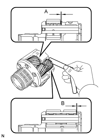
| 12. INSPECT PLANETARY GEAR ASSEMBLY |
Using a feeler gauge, measure the clearance between the planetary gear case and each pinion gear at points A and B.
-
| Standard Clearance
|
A point
| 0.23 to 0.59 mm (0.0091 to 0.0232 in.)
|
B point
| 0.16 to 0.66 mm (0.0063 to 0.02598 in.)
|
If the clearance is greater than the standard clearance, replace the planetary gear assembly.
| 13. INSPECT NO. 2 BRAKE DISC |
Check if the sliding surfaces of the discs, plates, and flange are worn or burnt. If necessary, replace them.
- NOTICE:
- If the linings of the discs are peeled off or discolored, or even if a part of the groove is damaged, replace all discs.
| 14. INSPECT 1ST AND REVERSE BRAKE RETURN SPRING SUB-ASSEMBLY |
Using vernier calipers, measure the free length of the 1st and reverse brake return spring together with the spring seat.
- Standard free length:
- 15.79 mm (0.6217 in.)
If the free length is shorter than the standard free length, replace the 1st and reverse brake return spring.
| 15. INSPECT CLEARANCE OF NO. 2 BRAKE |
Using a dial indicator, measure the clearance of the No. 2 brake while applying compressed air (200 kPa, 2.0 kgf/cm2, 29 psi).
- Standard clearance:
- 0.884 to 1.196 mm (0.0348 to 0.0471 in.)
- HINT:
- Measure the clearance at 3 points where the brake piston diameter is approximately 140 mm (5.51 in.) and calculate the average.
If the clearance is not as specified, select an appropriate No. 2 brake flange so that the clearance will be within the specified range.
- HINT:
- There are 5 different thicknesses of flanges available.
No. 2 brake flange thickness: mm (in)Thickness
| Thickness
|
4.0 (0.157)
| 4.3 (0.169)
|
4.1 (0.161)
| 4.4 (0.173)
|
4.2 (0.165)
| -
|
| 16. INSPECT CLEARANCE OF NO. 1 BRAKE |
Using a dial indicator, measure the clearance of the No. 1 brake while applying compressed air (200 kPa, 2.0 kgf/cm2, 29 psi).
- Standard clearance:
- 0.807 to 0.974 mm (0.0318 to 0.0383 in.)
- HINT:
- Measure the clearance at 3 points where the brake piston diameter is approximately 140 mm (5.51 in.) and calculate the average.
If the clearance is not as specified, select an appropriate No. 1 brake flange so that the clearance will be within the specified range.
- HINT:
- There are 6 different thicknesses of flanges available.
No. 1 brake flange thickness: mm (in.)Thickness
| Thickness
|
3.0 (0.118)
| 3.3 (0.130)
|
3.1 (0.122)
| 3.4 (0.134)
|
3.2 (0.126)
| 3.5 (0.138)
|
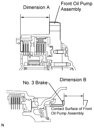
| 17. INSPECT CLEARANCE OF NO. 3 BRAKE |
Using vernier calipers and a straight edge, measure the distance shown in the illustration (Dimension A) while a load of 500 N (51 kgf, 112 lbf) is being applied to the flange.
- HINT:
- Measure dimension A at 3 points where the flange diameter is approximately 166 mm (6.54 in.) and calculate the average.
Using vernier calipers and a straight edge, measure the distance shown in the illustration. (Dimension B).
- HINT:
- Measure dimension B at 3 points where the No. 3 brake diameter is approximately 166 mm (6.54 in.) and calculate the average.
Calculate the clearance value using the following formula:
clearance = Dimension B - Dimension A
- Standard clearance:
- 0.599 to 0.761 mm (0.0236 to 0.0300 in.)
If the clearance is not as specified, select an appropriate brake flange so that the clearance will be within the specified range.
- HINT:
- There are 6 different thicknesses of flanges available.
No. 3 brake flange thickness: mm (in.)Thickness
| Thickness
|
3.80 (0.150)
| 4.10 (0.161)
|
3.90 (0.154)
| 4.20 (0.165)
|
4.00 (0.157)
| 4.30 (0.169)
|
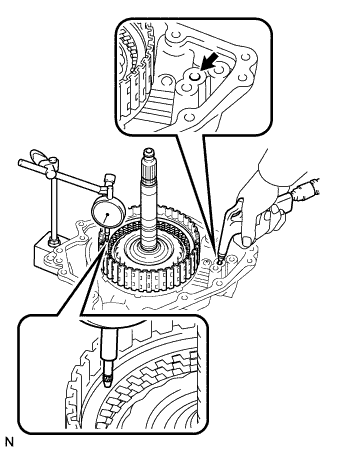
| 18. INSPECT CLEARANCE OF NO. 1 CLUTCH DISC |
Install the direct multiple disc clutch assembly onto the transaxle rear cover.
Using a dial indicator, measure the No. 1 clutch pack clearance while applying and releasing compressed air (200 kPa, 2.0 kgf/cm2, 29 psi).
- HINT:
- Measure the clearance at 3 points where the flange diameter is approximately 152 mm (5.98 in.) and calculate the average.
- Pack clearance:
- 0.806 to 0.974 mm (0.0317 to 0.0383 in.)
If the pack clearance is not as specified, inspect the discs, plates and flange.
- HINT:
- There are 6 different thicknesses of flanges available.
No. 1 clutch flange thickness: mm (in.)Thickness
| Thickness
|
3.0 (0.118)
| 3.3 (0.130)
|
3.1 (0.122)
| 3.4 (0.134)
|
3.2 (0.126)
| 3.5 (0.138)
|
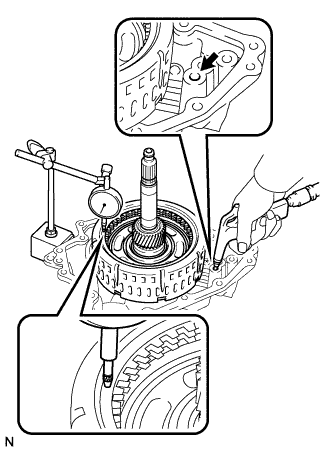
| 19. INSPECT CLEARANCE OF NO. 2 CLUTCH DISC |
Install the direct multiple disc clutch assembly onto the transaxle rear cover.
Using a dial indicator, measure the No. 2 clutch pack clearance while applying and releasing compressed air (200 kPa, 2.0 kgf/cm2, 29 psi).
- HINT:
- Measure the clearance at 3 points where the diameter of the No. 2 direct multiple clutch piston is approximately 152 mm (5.98 in.) and calculate the average.
- Pack clearance:
- 0.544 to 0.744 mm (0.0214 to 0.0293 in.)
If the pack clearance is not as specified, inspect the discs, plates and flange.
- HINT:
- There are 6 different thicknesses of flanges available.
No. 2 clutch flange thickness: mm (in.)Thickness
| Thickness
|
3.0 (0.118)
| 3.3 (0.130)
|
3.1 (0.122)
| 3.4 (0.134)
|
3.2 (0.126)
| 3.5 (0.138)
|