Dtc P0711 Transmission Fluid Temperature Sensor A Performance
DESCRIPTION
MONITOR DESCRIPTION
WIRING DIAGRAM
INSPECTION PROCEDURE
CHECK OTHER DTCS OUTPUT (IN ADDITION TO DTC P0711)
CHECK TRANSMISSION FLUID LEVEL
INSPECT TRANSMISSION WIRE
CHECK ATF TEMPERATURE SENSOR
DTC P0711 Transmission Fluid Temperature Sensor "A" Performance |
DESCRIPTION
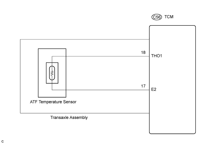
The ATF (Automatic Transmission Fluid) temperature sensor converts the fluid temperature into a resistance value for use by the TCM. The TCM applies a voltage to the temperature sensor through terminal OIL of the TCM.The sensor resistance changes with the transmission fluid temperature. As the temperature becomes higher, the sensor resistance decreases.One terminal of the sensor is grounded so that the sensor resistance decreases and the voltage goes down as the temperature becomes higher.The TCM calculates the fluid temperature based on the voltage signal.
DTC No.
| DTC Detection Condition
| Trouble Area
|
P0711
| - Both (a) and (b) are detected (2-trip detection logic):
- (a) Intake air and engine coolant temperature are more than -10°C (14°F) at engine start.
- (b) After normal driving for over 16 min. and 40 sec. and 5 mile (8 km) or more, ATF temperature is less than 20°C (68°F).
| - Transmission wire
- ATF temperature sensor
- TCM
|
MONITOR DESCRIPTION
This DTC indicates that there is a problem with output signals from the automatic transmission fluid (ATF) temperature sensor (TFT sensor) and that the sensor itself is defective. The ATF temperature sensor converts the ATF temperature into an electrical resistance value. Based on the resistance, the TCM determines the ATF temperature and detects an open or short in the ATF temperature circuit or a fault of the ATF temperature sensor.After running the vehicle for a certain period, the ATF temperature should increase. If the ATF temperature is below 20°C (68°F) after running the vehicle for a certain period, the TCM interprets this as a fault, and turns on the MIL.
WIRING DIAGRAM
INSPECTION PROCEDURE
- HINT:
- According to the Data List displayed on the intelligent tester, you can read the value of switches, sensors, actuators and other items without removing any parts. Reading the Data List as the first step in troubleshooting is one method to save labor time.
- NOTICE:
- In the table below, the values listed under "Normal Condition" are reference values. Do not depend solely on these reference values when deciding whether a part is faulty.
Warm up the engine.
Turn the ignition switch off.
Connect the intelligent tester to the DLC3.
Turn the ignition switch on.
Turn on the tester.
Enter the following items: "Powertrain / ECT / Data List".
According to the display on the tester, read "Data List".
Item
| Measurement Item/
Range (display)
| Normal Condition
|
Oil Temperature 1
| ATF Temperature Sensor Value/
min.: -40°C (-40°F)
max.: 215°C (419°F)
| - After Stall Test;
Approx. 80°C (176°F)
- Equal to ambient temperature when cold soak
|
- HINT:
- When DTC P0712 is output and the intelligent tester indicates 150°C (302°F) or more, there is a short circuit.
- When DTC P0713 is output and the intelligent tester indicates -40°C (-40°F), there is an open circuit.
- Measure the resistance between terminal THO1 (OT) and body ground.
Temperature Displayed
| Malfunction
|
-40°C (-40°F)
| Open circuit
|
150°C (302°F) or more
| Short circuit
|
- HINT:
- If a circuit related to the ATF temperature sensor becomes open, P0713 is immediately set (in 0.5 seconds). When P0713 is set, P0711 cannot be detected.
- It is not necessary to inspect the circuit when P0711 is set.
| 1.CHECK OTHER DTCS OUTPUT (IN ADDITION TO DTC P0711) |
Connect the the intelligent tester to the DLC3.
Turn the ignition switch on and turn the the intelligent tester on.
Select the items: "Powertrain / ECT / DTC / Current or Pending".
Read the DTCs using the intelligent tester.
- Result:
Display (DTC output)
| Proceed to
|
Only "P0711" is output
| A
|
"P0711" and other DTCs
| B
|
- HINT:
- If any other codes besides "P0711" are output, perform troubleshooting for those DTCs first.
| 2.CHECK TRANSMISSION FLUID LEVEL |
Check the transmission fluid level (CAMRY_ACV40 RM0000013BU00VX.html).
- OK:
- Automatic transmission fluid level is correct.
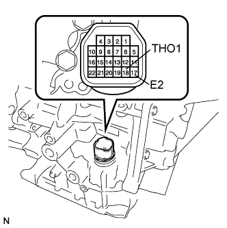
| 3.INSPECT TRANSMISSION WIRE |
Remove the TCM from the transaxle.
Measure the resistance according to the value(s) in the table below.
- Standard resistance:
Tester Connection
| Specified Condition
|
17 (E2) - 18 (THO1)
| 90 Ω to 156 kΩ
|
17 (E2) - Body ground
| 10 kΩ or higher
|
18 (THO1) - Body ground
| 10 kΩ or higher
|
- HINT:
- If the resistance is out of the specified range with the ATF temperature shown in the table below, the driveability of the vehicle may decrease.
- Standard resistance:
ATF Temperature
| Specified Condition
|
10°C (50°F)
| 5.8 to 7.1 kΩ
|
110°C (230°F)
| 0.22 to 0.28 kΩ
|
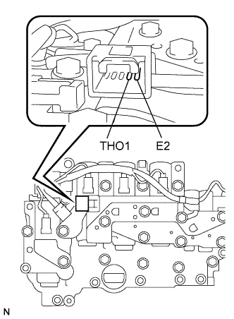
| 4.CHECK ATF TEMPERATURE SENSOR |
Disconnect the ATF temperature sensor connector from the transmission wire.
Measure the resistance according to the value(s) in the table below.
- Standard resistance:
Tester Connection
| Specified Condition
|
E2 - THO1
| 90 Ω to 156 kΩ
|
E2 - Body ground
| 10 kΩ or higher
|
THO1 - Body ground
| 10 kΩ or higher
|
- HINT:
- If the resistance is out of the specified range with the ATF temperature shown in the table below, the driveability of the vehicle may decrease.
- Standard resistance:
ATF Temperature
| Specified Condition
|
10°C (50°F)
| 5.8 to 7.1 kΩ
|
110°C (230°F)
| 0.22 to 0.28 kΩ
|
| | REPLACE ATF TEMPERATURE SENSOR ASSEMBLY |
|
|
| OK |
|
|
|
| REPLACE TRANSMISSION WIRE |
|