Dtc P0877 Transmission Fluid Pressure Sensor / Switch D Circuit Low
DESCRIPTION
WIRING DIAGRAM
INSPECTION PROCEDURE
CHECK OTHER DTC OUTPUT (IN ADDITION TO DTC P0877 OR P0878)
CHECK TRANSMISSION WIRE (SHORT TO GROUND)
CHECK ATF TEMPERATURE SENSOR ASSEMBLY (ATF PRESSURE SWITCH NO. 2)
CHECK TRANSMISSION WIRE
DTC P0877 Transmission Fluid Pressure Sensor / Switch "D" Circuit Low |
DTC P0878 Transmission Fluid Pressure Sensor / Switch "D" Circuit High |
DESCRIPTION
ATF pressure switch No. 2 is installed in the shift solenoid valve ATF output passage. This switch is used to identify the malfunctioning part when a fail-safe operation is performed. If the shift solenoid valve malfunctions when the ATF switch has a malfunction, a fail-safe operation will be performed. This fail-safe operation is different from the fail-safe operation performed when the solenoid valve malfunctions and the ATF switch is normal.DTC No.
| DTC Detecting Condition
| Trouble Area
|
P0877
| ATF pressure switch No. 2 OFF is detected twice when any of the gears from 4th to 6th engages normally.
| - ATF temperature sensor assembly (ATF pressure switch No. 2)
- Transmission wire
- TCM
|
P0878
| ATF pressure switch No. 2 ON is detected twice when any of the gears from 1st to 3rd engages normally.
|
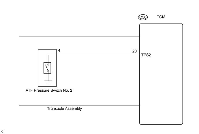
WIRING DIAGRAM
INSPECTION PROCEDURE
| 1.CHECK OTHER DTC OUTPUT (IN ADDITION TO DTC P0877 OR P0878) |
Connect the intelligent tester to the DLC3.
Turn the ignition switch on and turn the intelligent tester on.
Enter the following items: "Powertrain / ECT / DTC / Current or Pending".
Read the DTCs using the intelligent tester.
- Result:
Display (DTC output)
| Proceed to
|
Only "P0878" is output
| A
|
Only "P0877" is output
| B
|
"P0877 or P0878" and other DTCs
| C
|
- HINT:
- If a solenoid is stuck OFF, DTCs for several solenoids including the malfunctioning solenoid will be detected.
| 2.CHECK TRANSMISSION WIRE (SHORT TO GROUND) |
Remove the TCM.
Measure the resistance according to the value(s) in the table below.
- Standard resistance:
Tester Condition
| Specified Condition
|
20 (TPS2) - Body ground (Valve body assembly)
| 10 kΩ or higher
|
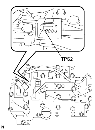
| 3.CHECK ATF TEMPERATURE SENSOR ASSEMBLY (ATF PRESSURE SWITCH NO. 2) |
Disconnect the connector from the ATF temperature sensor assembly.
Measure the resistance according to the value(s) in the table below.
- Standard resistance:
Tester Condition
| Specified Condition
|
4 (TPS2) - Body ground (Valve body assembly)
| 10 kΩ or higher
|
| | REPLACE ATF TEMPERATURE SENSOR ASSEMBLY |
|
|
| OK |
|
|
|
| REPLACE TRANSMISSION WIRE |
|
| 4.CHECK TRANSMISSION WIRE |
Remove the TCM.
Disconnect the speed sensor connector from the transmission wire.
Measure the resistance according to the value(s) in the table below.
- Standard resistance:
Tester Condition
| Specified Condition
|
20 (TPS2) - 4 (TPS2)
| Below 1 Ω
|
20 (TPS2) or 4 (TPS2) - Body ground (Valve body assembly)
| 10 kΩ or higher
|
| | REPLACE TRANSMISSION WIRE |
|
|
| OK |
|
|
|
| REPLACE ATF TEMPERATURE SENSOR ASSEMBLY |
|