Automatic Transaxle Unit Reassembly
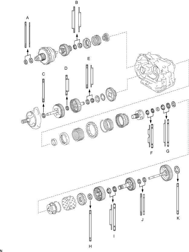
BEARING POSITION
INSTALL DIFFERENTIAL GEAR LUBE APPLY TUBE
INSTALL NO. 1 TRANSAXLE CASE PLUG
INSTALL UNDERDRIVE OUTPUT SHAFT OIL SEAL RING
INSTALL UNDERDRIVE CYLINDRICAL ROLLER BEARING
INSTALL UNDERDRIVE CLUTCH DRUM OIL SEAL RING
INSTALL NEEDLE ROLLER BEARING
INSTALL UNDERDRIVE BRAKE PISTON
INSTALL UNDERDRIVE BRAKE RETURN SPRING SUB-ASSEMBLY
INSTALL COUNTER DRIVE GEAR BEARING
INSTALL COUNTER DRIVE GEAR
INSTALL 1ST AND REVERSE BRAKE PISTON
INSTALL 1ST AND REVERSE BRAKE RETURN SPRING SUB-ASSEMBLY
INSTALL FRONT PLANETARY RING GEAR
INSTALL FRONT PLANETARY GEAR ASSEMBLY
INSTALL INPUT SUN GEAR
INSTALL REAR PLANETARY GEAR ASSEMBLY
INSTALL 1ST AND REVERSE BRAKE DISC
INSPECT PACK CLEARANCE OF FIRST AND REVERSE BRAKE
INSTALL 2ND BRAKE PISTON
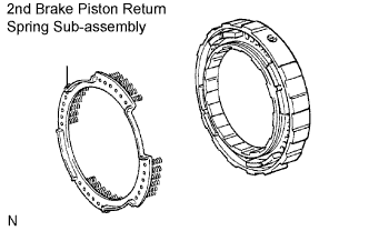
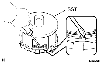
INSTALL 2ND BRAKE PISTON RETURN SPRING SUB-ASSEMBLY
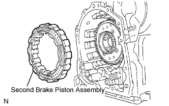
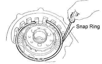
INSTALL SECOND BRAKE PISTON ASSEMBLY
INSTALL ONE-WAY CLUTCH SLEEVE
INSTALL NO. 1 PLANETARY CARRIER THRUST WASHER
INSTALL ONE-WAY CLUTCH ASSEMBLY
INSTALL REAR PLANETARY SUN GEAR ASSEMBLY
INSTALL 2ND BRAKE CLUTCH DISC
INSPECT PACK CLEARANCE OF SECOND BRAKE
INSTALL OVERDRIVE DIRECT CLUTCH HUB SUB-ASSEMBLY
INSTALL OVERDRIVE DIRECT CLUTCH O-RING
INSTALL OVERDRIVE DIRECT CLUTCH DRUM SUB-ASSEMBLY
INSTALL OVERDRIVE DIRECT CLUTCH PISTON
INSTALL OVERDRIVE CLUTCH RETURN SPRING SUB-ASSEMBLY
INSTALL OVERDRIVE DIRECT CLUTCH DISC
INSTALL DIRECT MULTIPLE DISC CLUTCH DISC
INSPECT PACK CLEARANCE OF DIRECT CLUTCH
INSPECT PACK CLEARANCE OF OVERDRIVE CLUTCH
INSTALL DIRECT CLUTCH ASSEMBLY
INSTALL NO. 1 GOVERNOR APPLY GASKET
INSTALL BRAKE APPLY TUBE
INSTALL NEEDLE ROLLER BEARING
INSTALL REAR CLUTCH OIL SEAL RING OUTER
INSTALL NO. 1 TRANSAXLE CASE PLUG
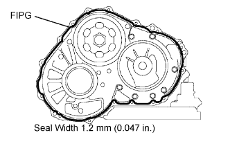
INSTALL TRANSAXLE REAR COVER SUB-ASSEMBLY
INSTALL NO. 2 UNDERDRIVE CLUTCH DISC
INSPECT PACK CLEARANCE OF NO. 2 UNDERDRIVE CLUTCH
INSPECT UNDERDRIVE ONE-WAY CLUTCH ASSEMBLY
INSTALL UNDERDRIVE ONE-WAY CLUTCH ASSEMBLY
INSTALL UNDERDRIVE CLUTCH ASSEMBLY
INSTALL PARKING LOCK PAWL
INSTALL UNDERDRIVE PLANETARY GEAR ASSEMBLY
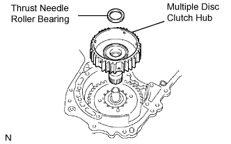
INSTALL MULTIPLE DISC CLUTCH HUB
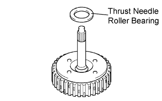
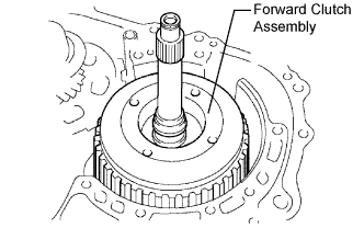
INSTALL FORWARD CLUTCH ASSEMBLY
INSTALL OVERDRIVE BRAKE GASKET
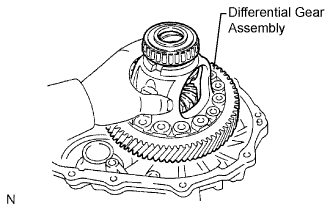
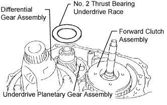
INSTALL DIFFERENTIAL GEAR ASSEMBLY
INSTALL NO. 2 THRUST BEARING UNDERDRIVE RACE
INSTALL THRUST NEEDLE ROLLER BEARING
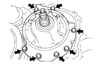
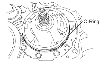
INSTALL OIL PUMP ASSEMBLY
INSTALL TRANSAXLE HOUSING
INSPECT INPUT SHAFT END PLAY
FIX AUTOMATIC TRANSAXLE ASSEMBLY
INSTALL MANUAL VALVE LEVER SHAFT OIL SEAL
INSTALL PARKING LOCK ROD SUB-ASSEMBLY
INSTALL MANUAL VALVE LEVER SUB-ASSEMBLY
INSTALL MANUAL VALVE LEVER SHAFT RETAINER SPRING
INSTALL PARKING LOCK PAWL BRACKET
INSTALL MANUAL DETENT SPRING SUB-ASSEMBLY
INSTALL B-3 ACCUMULATOR PISTON
INSTALL REVERSE CLUTCH ACCUMULATOR PISTON
INSTALL C-3 ACCUMULATOR PISTON
INSTALL CHECK BALL BODY
INSTALL BRAKE DRUM GASKET
INSTALL TRANSAXLE CASE 2ND BRAKE GASKET
INSTALL NO. 1 GOVERNOR APPLY GASKET
INSTALL TRANSMISSION VALVE BODY ASSEMBLY
INSTALL VALVE BODY OIL STRAINER ASSEMBLY
INSTALL TRANSMISSION WIRE
CONNECT TRANSMISSION WIRE
INSTALL AUTOMATIC TRANSAXLE OIL PAN SUB-ASSEMBLY
INSTALL NO. 1 TRANSAXLE CASE PLUG
INSTALL SPEED SENSOR
INSTALL OIL COOLER TUBE UNION (OUTLET OIL COOLER UNION)
INSTALL OIL COOLER TUBE UNION (INLET OIL COOLER UNION)
INSTALL NO. 2 BREATHER PLUG
INSTALL PARK/NEUTRAL POSITION SWITCH ASSEMBLY
Automatic Transaxle Unit -- Reassembly |
Mark
| Front Race Diameter
Inside / Outside (mm (in.))
| Thrust Bearing Diameter
Inside / Outside (mm (in.))
| Rear Race Diameter
Inside / Outside (mm (in.))
|
A
| -
| 53.0 (2.087) / 78.2 (3.079)
| 52.1 (2.051) / 75.5 (2.972)
|
B
| -
| 37.73 (1.4854) / 58.0 (2.284)
| 29.9 (1.177) / 55.5 (2.185)
|
C
| -
| 33.85 (1.3327) / 52.2 (2.055)
| -
|
D
| -
| 23.5 (0.925) / 44.0 (1.732)
| -
|
E
| -
| 36.3 (1.429) / 52.2 (2.055)
| 34.5 (1.358) / 48.5 (1.909)
|
F
| 34.5 (1.358) / 56.82 (2.2370)
| 32.4 (1.276) / 56.62 (2.2291)
| -
|
G
| 40.3 (1.587) / 58.0 (2.284)
| 38.6 (1.520) / 60.0 (2.362)
| 38.6 (1.520) / 58.0 (2.284)
|
H
| -
| 53.6 (2.110) / 69.6 (2.740)
| -
|
I
| 33.1 (1.303) / 45.4 (1.787)
| 31.85 (1.2539) / 45.2 (1.780)
| -
|
J
| -
| 25.0 (0.984) / 39.5 (1.555)
| 23.6 (0.929) / 36.6 (1.441)
|
K
| -
| 55.9 (2.201) / 76.0 (2.992) or 76.6 (3.016)
| -
|
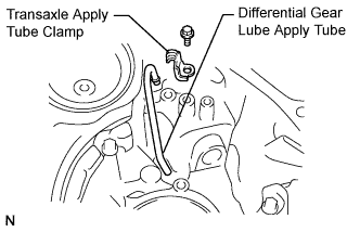
| 2. INSTALL DIFFERENTIAL GEAR LUBE APPLY TUBE |
Install the differential gear lube apply tube and transaxle apply tube clamp to the transaxle housing with the bolt.
- Torque:
- 9.8 N*m{100 kgf*cm, 87 in.*lbf}
- NOTICE:
- Make sure to insert the pipe to the stopper.
| 3. INSTALL NO. 1 TRANSAXLE CASE PLUG |
Install 2 new O-rings to the 2 No. 1 transaxle case plugs.
Install the 2 No. 1 transaxle case plugs to the transaxle rear housing.
- Torque:
- 7.4 N*m{75 kgf*cm, 65 in.*lbf}
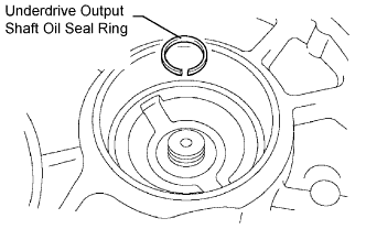
| 4. INSTALL UNDERDRIVE OUTPUT SHAFT OIL SEAL RING |
Coat a new oil seal ring with ATF and install it to the transaxle housing.
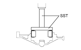
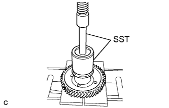
| 5. INSTALL UNDERDRIVE CYLINDRICAL ROLLER BEARING |
Coat the underdrive cylindrical roller bearing with ATF.
Using SST and a press, install the underdrive cylindrical roller bearing.
- SST
- 09950-60020
09950-70010(09951-00780,09951-07100)
- NOTICE:
- Do not apply excessive pressure to it.
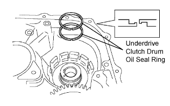
| 6. INSTALL UNDERDRIVE CLUTCH DRUM OIL SEAL RING |
Coat 2 new oil seal rings with ATF, and install them to the transaxle rear cover.
- NOTICE:
- Do not expand the gap of the oil seal ring excessively.
- Securely engage the hooks. Confirm the smooth rotation.
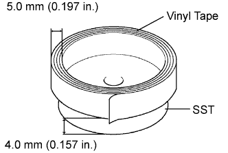
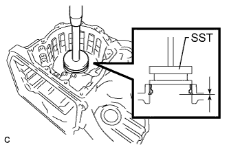
| 7. INSTALL NEEDLE ROLLER BEARING |
Wind vinyl tape around SST at the place 4.0 mm (0.157 in.) above the bottom end until the thickness of the wound tape is about 5.0 mm (0.197 in.).
- NOTICE:
- Clean SST to remove deposited oil before winding vinyl tape.
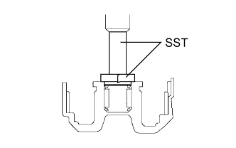
Coat a new needle roller bearing with ATF.
Using SST and a press, install the needle roller bearing to the transaxle case.
- SST
- 09950-60010(09951-00320)
09950-70010(09951-07100)
- NOTICE:
- When the wound vinyl tape contacts the transaxle case, stop press-fitting.
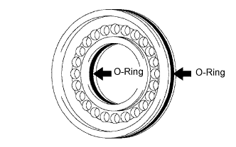
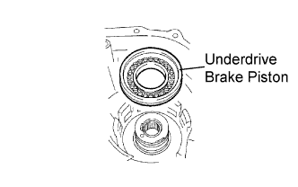
| 8. INSTALL UNDERDRIVE BRAKE PISTON |
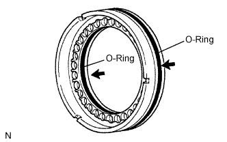
Coat 2 new O-rings with ATF, and install them to the underdrive brake piston.
- NOTICE:
- Install the the O-rings carefully not to have a twist or a pinching.
- Apply enough ATF to the O-rings prior to installation.
Coat the underdrive brake piston with ATF.
Install the underdrive brake piston to the transaxle case.
- NOTICE:
- Be careful not to damage the O-rings.
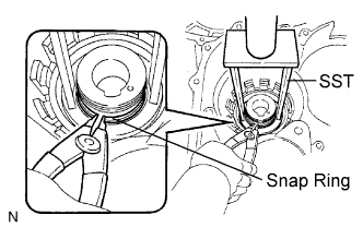
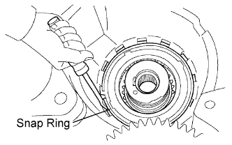
| 9. INSTALL UNDERDRIVE BRAKE RETURN SPRING SUB-ASSEMBLY |
Place SST on the return spring and compress the return spring with a press.
- SST
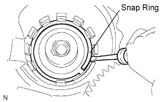
- 09387-00020
Using a snap ring expander, install the snap ring to the transaxle case.
- NOTICE:
- Stop the press when the spring seat is lowered to the place 1 to 2 mm (0.039 to 0.078 in.) from the snap ring groove to prevent the spring seat from being deformed.
- Do not expand the snap ring excessively.
- After installing the spring sub-assembly, check all of the springs are fitted in the piston correctly.
- The snap ring should be securely engaged in the groove of the transaxle case.
| 10. INSTALL COUNTER DRIVE GEAR BEARING |
Install the snap ring to the transaxle case.
Using SST and a press, install the bearing outer race (rear side) to the transaxle case.
- SST
- 09316-12010
09950-60020(09951-00810)
09950-70010(09951-07150)
- NOTICE:
- Ensure that the snap ring is securely installed.
- Do not apply excessive pressure to the bearing outer race.
Using SST and a press, install the bearing outer race (front side) to the transaxle case.
- SST
- 09316-12010
09502-24010
09523-36010
09950-60020(09951-00810)
09950-70010(09951-07150)
- NOTICE:
- Do not apply excessive pressure to the bearing outer race.
- Install the bearing outer race with a press while holding the bearing outer race with SST (09502-24010, 09523-36010).
Install the 2 angular balls to the transaxle case.
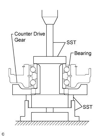
| 11. INSTALL COUNTER DRIVE GEAR |
Coat the counter drive gear with ATF.
Using SST and a press, install the tapered roller bearing inner race (front side) to the counter drive gear.
- SST
- 09649-17010
09950-70010(09951-07150)
- NOTICE:
- Do not apply excessive pressure to the bearing inner race.
Using SST and a press, install the counter drive gear and bearing inner race (rear side) to the transaxle case.
- SST
- 09223-15030
09527-17011
09950-60020(09951-00720)
09950-70010(09951-07150)
- NOTICE:
- Do not apply excessive pressure to the counter drive gear and bearing inner race.
| 12. INSTALL 1ST AND REVERSE BRAKE PISTON |
Coat 2 new O-rings with ATF.
Install the 2 O-rings to the 1st and reverse brake piston.
- NOTICE:
- Install the O-rings carefully not to have a twist or a pinching.
- Apply enough ATF to the O-rings prior to installation.
Coat the 1st and reverse brake piston with ATF, and install it to the transaxle case.
- NOTICE:
- Be careful not to damage the O-rings.
| 13. INSTALL 1ST AND REVERSE BRAKE RETURN SPRING SUB-ASSEMBLY |
Install the return spring.
Place SST on the return spring and compress the return spring with a press.
- SST
- 09387-00070
Using a snap ring expander, install the snap ring to the transaxle case.
- NOTICE:
- Stop the press when the spring seat is lowered to the place 1 to 2 mm (0.039 to 0.078 in.) from the snap ring groove to prevent the spring seat from being deformed.
- Do not expand the snap ring excessively.
- After installing the spring sub-assembly, check all of the springs are fitted in the piston correctly.
- The snap ring should be securely engaged in the groove of the cylinder.
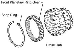
| 14. INSTALL FRONT PLANETARY RING GEAR |
Using a screwdriver, install the front planetary ring gear and snap ring to the brake hub.
- NOTICE:
- Confirm that the snap ring is engaged in the groove of the brake hub correctly.
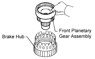
| 15. INSTALL FRONT PLANETARY GEAR ASSEMBLY |
Install the front planetary gear assembly to the brake hub.
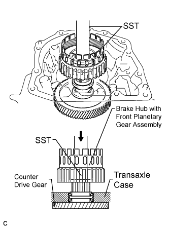
Using SST and a press, press-fit the front planetary gear assembly.
- SST
- 09950-60010(09951-00500)
09950-70010(09951-07100)
- NOTICE:
- Do not apply excessive pressure to the front planetary gear assembly.
- Press the inner race of the LH tapered roller bearing, counter gear, and front planetary gear assembly to the position where no pre-load is applied to one pair of tapered roller bearings (left and right).
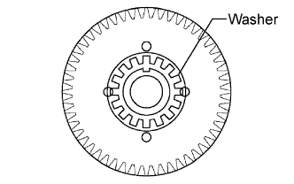
Install a new washer as shown in the illustration.
Using SST, install the nut.
- SST
- 09387-00030
09387-00080
- Torque:
- 185 N*m{1,886 kgf*cm, 136 ft.*lbf}
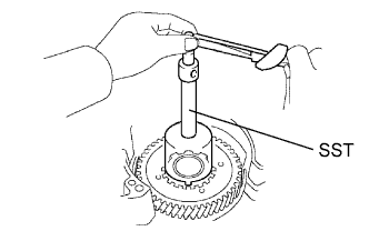
Using SST and a torque wrench, measure the turning torque of the bearing while rotating SST at 60 rpm. If the measured value is not within the specified range, gradually tighten the nut until the turning torque falls within the specified range.
- SST
- 09387-00080
- Torque:
- 350 N*m{3,569 kgf*cm, 258 ft.*lbf}(a limit)
- Bearing Turning Torque:
- 0.19 to 0.4 N*m (1.9 to 4.1 kgf*cm, 1.7 to 3.5 in.*lbf)
- HINT:
- Use a torque wrench with a fulcrum length of 160 mm (6.3 in.) to measure the turning torque.
Using a chisel and hammer, stake the front lock washer.
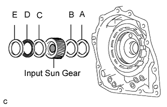
| 16. INSTALL INPUT SUN GEAR |
Coat the 2 thrust bearings with ATF.
Install the input sun gear, 2 thrust needle roller bearings, 2 No. 2 thrust bearing races, and No. 3 thrust bearings to the transaxle case.
- NOTICE:
- Ensure that the parts are installed in the correct order and direction.
Thrust bearing and bearing race diameter: mm (in.)
| Inside
| Outside
|
Bearing Race, A
| 34.5 (1.358)
| 56.82 (2.2370)
|
Thrust Bearing, B
| 32.4 (1.276)
| 56.62 (2.2291)
|
Bearing Race, C
| 40.3 (1.587)
| 58.0 (2.284)
|
Thrust Bearing, D
| 38.6 (1.520)
| 60.0 (2.362)
|
Bearing Race, E
| 38.6 (1.520)
| 58.0 (2.284)
|
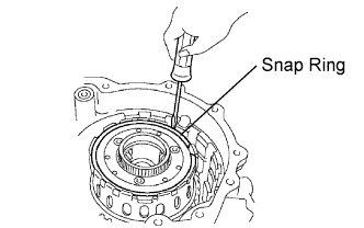
| 17. INSTALL REAR PLANETARY GEAR ASSEMBLY |
Install the rear planetary gear assembly to the brake hub.
Using a screwdriver, install the snap ring.
- NOTICE:
- Confirm that the snap ring is engaged in the groove of the 1st and reverse brake hub correctly.
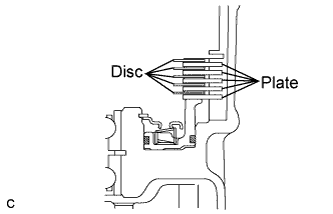
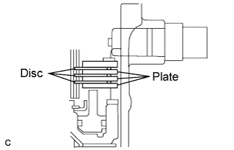
| 18. INSTALL 1ST AND REVERSE BRAKE DISC |
Coat the 5 discs with ATF.
Install the 5 plates and 5 discs.
- NOTICE:
- Be careful about the order of discs and plates.
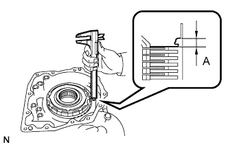
| 19. INSPECT PACK CLEARANCE OF FIRST AND REVERSE BRAKE |
Using vernier calipers, measure the distance between the disc surface and the contact surface of the 2nd brake cylinder and transaxle case (Dimension A).
Select an appropriate flange so that the pack clearance will be within the specified range.
- Pack clearance:
- 0.745 to 1.21 mm (0.0293 to 0.0476 in.)
- HINT:
- Piston stroke = Dimension A - Flange thickness
Flange thickness: mm (in.)Mark
| Thickness
| Mark
| Thickness
|
1
| 1.8 (0.071)
| 5
| 2.2 (0.087)
|
2
| 1.9 (0.075)
| 6
| 2.3 (0.091)
|
3
| 2.0 (0.079)
| 7
| 2.4 (0.094)
|
4
| 2.1 (0.083)
| 8
| 2.5 (0.098)
|
Install the flange.
| 20. INSTALL 2ND BRAKE PISTON |
Coat the 2nd brake piston with ATF, and install it to the 2nd brake cylinder.
| 21. INSTALL 2ND BRAKE PISTON RETURN SPRING SUB-ASSEMBLY |
Install the 2nd brake piston return spring sub-assembly.
- NOTICE:
- Ensure that all springs are fitted in the piston correctly.
Place SST on the piston return spring, and compress it with a press.
- SST
- 09387-00060
Using a screwdriver, install the snap ring.
- NOTICE:
- Stop the press when the spring seat is lowered to the place 1 to 2 mm (0.039 to 0.078 in.) from the snap ring groove. This prevents the spring seat from being deformed.
| 22. INSTALL SECOND BRAKE PISTON ASSEMBLY |
Install the second brake piston assembly to the transaxle case.
Install the snap ring and measure the inside diameter.
- Inside diameter:
- More than 167 mm (6.57 in.)
- NOTICE:
- Make sure to install the tapered snap ring in the correct direction.
- When the diameter does not meet the specified value, replace the snap ring with a new one.
- After installing the snap ring, confirm that there is no clearance between the second brake cylinder and the fitting surface of the cylinder in the transaxle case.
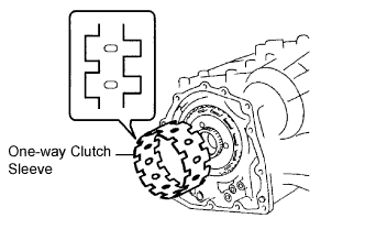
| 23. INSTALL ONE-WAY CLUTCH SLEEVE |
Install the one-way clutch sleeve to the 2nd brake cylinder assembly.
- NOTICE:
- Check the positioning direction of the outer sleeve.
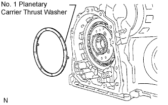
| 24. INSTALL NO. 1 PLANETARY CARRIER THRUST WASHER |
Coat the No. 1 planetary carrier thrust washer with ATF, and install it onto the planetary sun gear assembly.
- NOTICE:
- After installing the washer, confirm that the projections on the washer are securely fitted in the holes of the planetary sun gear assembly.
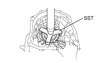
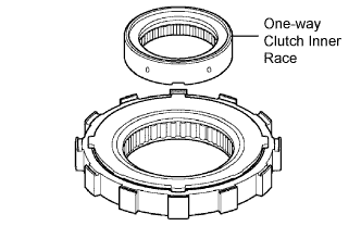
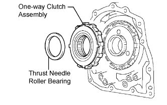
| 25. INSTALL ONE-WAY CLUTCH ASSEMBLY |
Install the one-way clutch inner race to the one-way clutch.
- NOTICE:
- Check the direction of the inner race.
- Confirm that the discrimination mark can be seen.
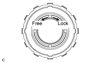
Check the rotating direction of the one-way clutch inner race for the lock or free operation, as shown in the illustration.
Install the one-way clutch and thrust needle roller bearing to the one-way clutch sleeve outer.
Bearing diameter: mm (in.)
| Inside
| Outside
|
Bearing
| 53.6 (2.110)
| 69.4 (2.732)
|
- NOTICE:
- Install the thrust bearing properly so that non-colored race will be visible.
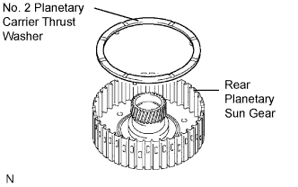
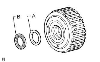
| 26. INSTALL REAR PLANETARY SUN GEAR ASSEMBLY |
Coat the No. 2 planetary carrier thrust washer with ATF, and install it onto the rear planetary sun gear.
Coat the bearing with yellow petrolatum, and install it onto the rear planetary sun gear.
Bearing diameter: mm (in.)
| Inside
| Outside
|
Race, A
| 33.1 (1.303)
| 45.4 (1.787)
|
Bearing, B
| 31.85 (1.254)
| 45.2 (1.78)
|
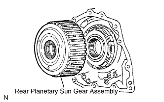
Install the rear planetary sun gear assembly to the rear planetary gear.
- NOTICE:
- After installing the rear planetary sun gear assembly, confirm that the B1 discs engage.
| 27. INSTALL 2ND BRAKE CLUTCH DISC |
Coat the 3 discs with ATF.
Install the 3 discs and 3 plates to the transaxle case.
Install the snap ring.
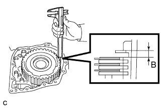
| 28. INSPECT PACK CLEARANCE OF SECOND BRAKE |
Using vernier calipers, measure the distance between the disc surface and snap ring surface (Dimension B).
Select an appropriate flange so that the pack clearance will be within the specified range.
- Pack clearance:
- 0.53 to 0.91 mm (0.0209 to 0.0358 in.)
- HINT:
- Piston stroke = Dimension B - Flange thickness - Snap ring thickness 1.6 mm (0.063 in.)
Flange thickness: mm (in.)Mark
| Thickness
| Mark
| Thickness
|
0
| 2.9 (0.114)
| 5
| 3.4 (0.134)
|
1
| 3.0 (0.118)
| 6
| 3.5 (0.138)
|
2
| 3.1 (0.122)
| 7
| 3.6 (0.142)
|
3
| 3.2 (0.126)
| 8
| 3.7 (0.146)
|
4
| 3.3 (0.130)
| -
| -
|
Install the flange.
| 29. INSTALL OVERDRIVE DIRECT CLUTCH HUB SUB-ASSEMBLY |
Install the direct clutch hub to the planetary gear assembly.
- NOTICE:
- Be careful not to damage the bushing inside the overdrive clutch hub during installation.
Coat the thrust bearing with ATF.
Install the bearing race and the thrust bearing to the direct clutch hub.
- NOTICE:
- When installing the bearing, hold the side of the overdrive clutch hub.
Bearing and race diameter: mm (in.)
| Inside
| Outside
|
Bearing, A
| 25.0 (0.984)
| 39.5 (1.555)
|
Race, B
| 23.6 (0.929)
| 36.6 (1.441)
|
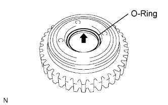
| 30. INSTALL OVERDRIVE DIRECT CLUTCH O-RING |
Coat a new O-ring with ATF, and install it to the direct clutch drum.
- NOTICE:
- Ensure that the O-ring is not twisted or pinched.
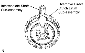
| 31. INSTALL OVERDRIVE DIRECT CLUTCH DRUM SUB-ASSEMBLY |
Coat the direct clutch drum with ATF, and install it to the intermediate shaft.
- NOTICE:
- Be careful not to damage the O-ring.
- Be careful not to damage the lip seal of the direct clutch drum.
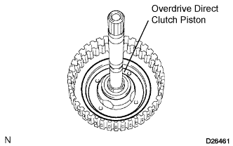
| 32. INSTALL OVERDRIVE DIRECT CLUTCH PISTON |
Coat the overdrive direct clutch piston with ATF, and install it to the overdrive direct clutch drum sub-assembly.
- NOTICE:
- Be careful not to damage the lip seal of the direct clutch piston.
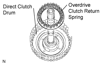
| 33. INSTALL OVERDRIVE CLUTCH RETURN SPRING SUB-ASSEMBLY |
Install the overdrive clutch return spring sub-assembly to the overdrive direct clutch drum sub-assembly.
- NOTICE:
- When installing the spring sub-assembly, ensure that all springs are fitted in the piston correctly.
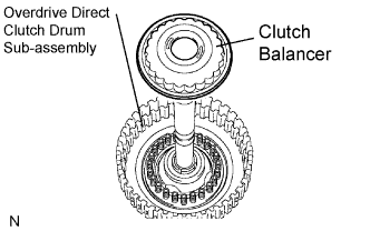
Coat the clutch balancer with ATF.
Install the clutch balancer to the overdrive direct clutch drum sub-assembly.
- NOTICE:
- Be careful not to damage the lip seal of the direct clutch balancer.
- Ensure that the clutch balancer is not pinched and there are no other defects at the sealing lip.
- Apply enough ATF to the sealing lip prior to installation.
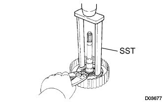
Place SST on the clutch balancer and compress the piston return spring with a press.
- SST
- 09387-00020
Using a snap ring expander, install the snap ring to the direct clutch drum.
- NOTICE:
- Stop the press when the spring seat is lowered to the place 1 to 2 mm (0.039 to 0.078 in.) from the snap ring groove. This prevents the spring seat from being deformed.
- Do not expand the snap ring excessively.
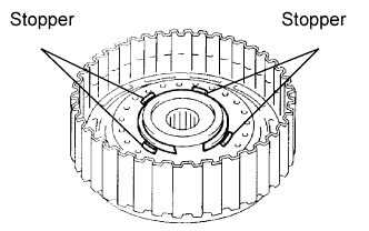
Position the end gap of the snap ring in the piston as shown in the illustration.
- NOTICE:
- Ensure that the end gap of the snap ring is not aligned with any of the stoppers.
| 34. INSTALL OVERDRIVE DIRECT CLUTCH DISC |
Coat the 3 discs with ATF.
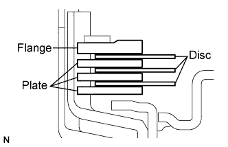
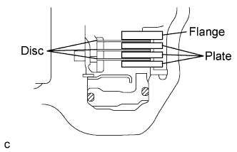
Install the 3 plates, 3 discs and flange to the intermediate shaft.
- NOTICE:
- Be careful about the order of the discs, plates and flange.
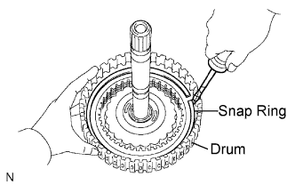
Using a screwdriver, install the snap ring.
- NOTICE:
- The snap ring should be securely engaged in the groove of the drum.
| 35. INSTALL DIRECT MULTIPLE DISC CLUTCH DISC |
Coat the 3 discs with ATF.
Install the cushion plate, 3 plates, 3 discs and flange to the intermediate shaft.
- NOTICE:
- Install the cushion plate with the mark on the white surface facing the plate.
- Be careful about the order of discs, plates and flange.
Using a screwdriver, install the snap ring.
- NOTICE:
- The snap ring should be securely engaged in the groove of the drum.
| 36. INSPECT PACK CLEARANCE OF DIRECT CLUTCH |
Install the intermediate shaft and needle roller bearing on the transaxle rear cover.
- NOTICE:
- Be careful not to damage the oil seal ring outers.
Using a dial indicator, measure the direct clutch pack clearance while applying and releasing compressed air (392 kPa, 4.0 kgf/cm2, 57 psi).
- Pack clearance:
- 0.60 to 0.82 mm (0.02362 to 0.03228 in.)
If the pack clearance is not as specified, inspect the discs, plates and flange.
| 37. INSPECT PACK CLEARANCE OF OVERDRIVE CLUTCH |
Using a dial indicator, measure the overdrive clutch pack clearance while applying and releasing compressed air (392 kPa, 4.0 kgf/cm2, 57 psi).
- Pack clearance:
- 0.52 to 0.83 mm (0.02047 to 0.03268 in.)
If the pack clearance is not as specified, inspect the discs, plates and flange.
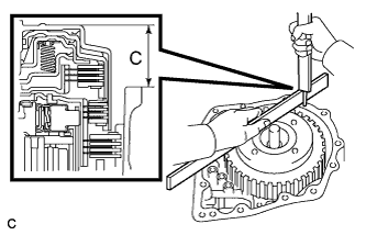
| 38. INSTALL DIRECT CLUTCH ASSEMBLY |
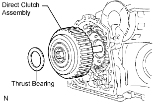
Coat the thrust bearing with ATF.
Install the direct clutch assembly and thrust bearing to the rear planetary sun gear assembly.
- NOTICE:
- The disc in the direct clutch should completely match with the hub attached outside the rear planetary sun gear. Otherwise, the rear cover cannot be installed.
Clean the contact surfaces of the transaxle case and the rear cover.
As shown in the illustration, place a straight edge on the direct clutch drum and measure the distance between the transaxle case and the straight edge using vernier calipers (Dimension C).
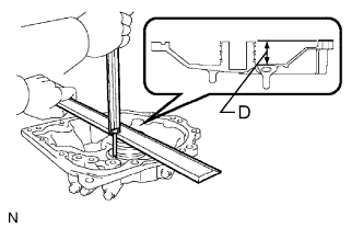
Using vernier calipers and a simple straight edge, measure the dimension shown in the illustration.
Calculate the end play value using the following formula. Select a thrust bearing which satisfies the specified end play value and install it.
- End play:
- 0.199 to 0.970 mm (0.0078 to 0.0382 in.)
- NOTICE:
- Make sure that the non-colored race side is facing the direct clutch assembly.
- HINT:
- End play = Dimension D - Dimension C
Bearing thickness and diameter: mm (in.)Thickness
| Inside
| Outside
|
3.6 (0.1417)
| 55.9 (2.201)
| 76.0 (2.992)
|
3.8 (0.150)
| 55.9 (2.201)
| 76.6 (3.016)
|
| 39. INSTALL NO. 1 GOVERNOR APPLY GASKET |
Install 3 new No. 1 governor apply gaskets to the transaxle case.
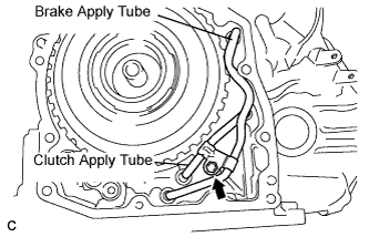
| 40. INSTALL BRAKE APPLY TUBE |
Install the clamp to the brake apply tube.
- NOTICE:
- Make sure to install the clamp to the apply tube before installing the apply tube to the transaxle case. This prevents the apply tube from being deformed or damaged.
Install the clutch apply tube.
Install the brake apply tube to the transaxle case with the bolt.
- Torque:
- 5.4 N*m{55 kgf*cm, 48 in.*lbf}
- NOTICE:
- Each pipe should be securely inserted until it reaches the stopper.
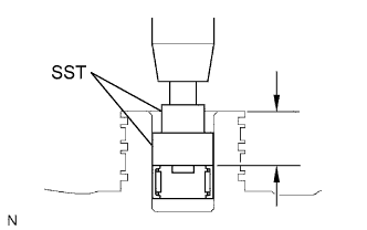
| 41. INSTALL NEEDLE ROLLER BEARING |
Using SST and a press, install the needle roller bearing to the transaxle rear cover.
- SST
- 09950-60010(09951-00230,09952-06010,09951-00360)
- Press fit depth:
- 20.55 to 21.25 mm (0.8091 to 0.8366 in.)
- NOTICE:
- Face the inscribed mark side of the bearing race up.
- Keep pressing until the specified value is obtained.
Coat the needle roller bearing with ATF.
| 42. INSTALL REAR CLUTCH OIL SEAL RING OUTER |
Coat 3 new rear clutch oil seal rings with ATF, and install them to the transaxle rear cover.
- NOTICE:
- The rear clutch oil seal rings should be securely engaged in the grooves of the drum.
| 43. INSTALL NO. 1 TRANSAXLE CASE PLUG |
Install 4 new O-rings to the 4 No. 1 transaxle case plugs.
Install the 4 No. 1 transaxle case plugs to the transaxle rear cover.
- Torque:
- 7.4 N*m{75 kgf*cm, 65 in.*lbf}
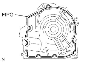
| 44. INSTALL TRANSAXLE REAR COVER SUB-ASSEMBLY |
Remove any packing material and keep the contact surfaces of the transaxle rear cover and the transaxle case away from oil.
Apply FIPG to the cover.
- FIPG:
- Toyota Genuine Seal Packing 1281, Three Bond 1281 or equivalent
- NOTICE:
- Apply FIPG in a continuous line (width 1.2 mm (0.047 in.)) along the sealing surface.
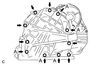
Apply adhesive or equivalent to the threads of bolt A.
- Adhesive:
- Toyota Genuine Adhesive 1344, Three Bond 1344 or equivalent
Install the 11 bolts.
- Torque:
- Bolt A:
- 19 N*m{190 kgf*cm, 14 ft.*lbf}
- Other bolts:
- 25 N*m{250 kgf*cm, 18 ft.*lbf}
- NOTICE:
- Apply adhesive to the bolts and tighten them within 10 minutes of application.
| 45. INSTALL NO. 2 UNDERDRIVE CLUTCH DISC |
Coat the 3 discs with ATF.
Install the 3 discs, 3 plates and flange to the transaxle case.
- NOTICE:
- Be careful about the order of discs, plates and flange.
Using a screwdriver, install the snap ring.
- NOTICE:
- The snap ring should be securely engaged in the groove of the drum.
| 46. INSPECT PACK CLEARANCE OF NO. 2 UNDERDRIVE CLUTCH |
Using a dial indicator, measure the underdrive clutch pack clearance while applying and releasing compressed air (392 kPa, 4.0 kgf/cm2, 57 psi).
- Pack clearance:
- 1.645 to 2.20 mm (0.0648 to 0.0866 in.)
Select an appropriate flange from the table below so that the pack clearance will be within the specified range.
Flange thickness: mm (in.)Mark
| Thickness
| Mark
| Thickness
|
Y
| 2.8 (0.110)
| C
| 3.4 (0.134)
|
A
| 3.0 (0.118)
| D
| 3.6 (0.142)
|
B
| 3.2 (0.126)
| -
| -
|
Temporarily remove the snap ring and attach the flange to the transaxle case.
Reinstall the snap ring to the transaxle case.
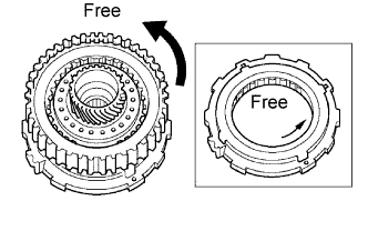
| 47. INSPECT UNDERDRIVE ONE-WAY CLUTCH ASSEMBLY |
Install the underdrive clutch assembly to the one-way clutch.
Rotate the underdrive clutch assembly to check the rotating direction for the lock or free operation.
Remove the underdrive clutch assembly from the one-way clutch.
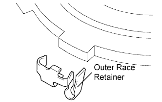
| 48. INSTALL UNDERDRIVE ONE-WAY CLUTCH ASSEMBLY |
Install the outer race retainer to the one-way clutch.
- NOTICE:
- Securely install the outer race retainer onto the external tooth of the one-way clutch.
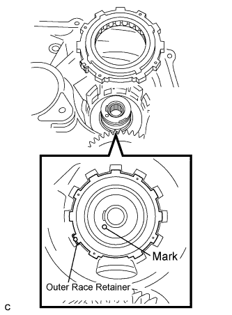
Install the one-way clutch to the transaxle case.
- NOTICE:
- Ensure that the outer race retainer and the mark on the transaxle case are aligned.
Using a screwdriver, install the snap ring to the transaxle case.
- NOTICE:
- The snap ring should be securely engaged in the groove of the transaxle case.
| 49. INSTALL UNDERDRIVE CLUTCH ASSEMBLY |
Coat the bearing and bearing race with ATF, and install them onto the underdrive clutch.
Bearing and bearing race diameter: mm (in.)
| Inside
| Outside
|
Bearing
| 37.73 (1.4854)
| 58.0 (2.284)
|
Race
| 29.9 (1.177)
| 55.5 (2.185)
|
Install the underdrive clutch assembly to the transaxle case.
- NOTICE:
- When installing the underdrive clutch drum sub-assembly, do not damage the oil seal ring.
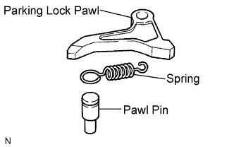
| 50. INSTALL PARKING LOCK PAWL |
Install the pawl pin and spring to the parking lock pawl.
Temporarily install the parking lock pawl, pin and spring to the transaxle case as shown in the illustration.
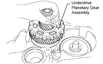
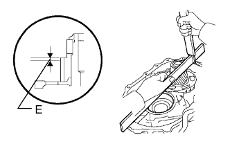
| 51. INSTALL UNDERDRIVE PLANETARY GEAR ASSEMBLY |
Install the underdrive planetary gear assembly to the transaxle case.
- NOTICE:
- Firmly engage all the discs of the underdrive clutch with the hub splines of the underdrive planetary gear assembly and securely assemble them.
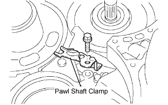
Install the parking lock pawl shaft.
Install the pawl shaft clamp with the bolt.
- Torque:
- 9.8 N*m{100 kgf*cm, 87 in.*lbf}
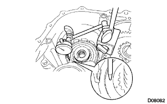
Using a straight edge and vernier calipers as shown in the illustration, measure the gap between the top of the differential drive pinion in the underdrive planetary gear and contact surface of the transaxle case and housing (Dimension E).
- NOTICE:
- Note down dimension E because it is necessary for the following process.
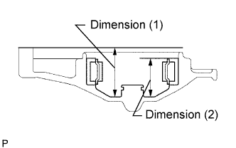
As shown in the illustration, measure the 2 places of the transaxle housing, and calculate dimension F using the following formula.
- NOTICE:
- Note down dimension F because it is necessary for the following process.
- HINT:
- Dimension F = Dimension (1) - Dimension (2)
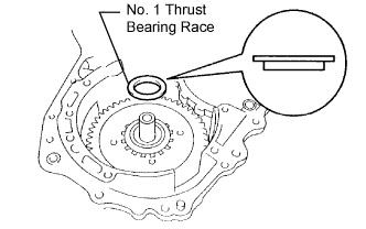
| 52. INSTALL MULTIPLE DISC CLUTCH HUB |
Install the No. 1 thrust bearing race to the transaxle case while checking its direction.
Bearing race diameter: mm (in.)
| Inside
| Outside
|
Bearing Race
| 34.5 (1.359)
| 48.5 (1.909)
|
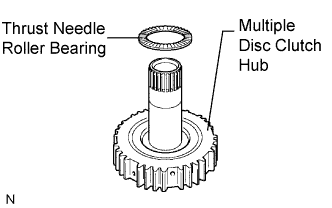
Coat the thrust needle roller bearing and race with ATF, and install them onto the multiple disc clutch hub.
Thrust bearing and race diameter: mm (in.)
| Inside
| Outside
|
Thrust Bearing
| 36.4 (1.433)
| 52.2 (2.055)
|
Coat the needle roller bearing with ATF.
Install the needle roller bearing to the multiple disc clutch hub.
Bearing diameter: mm (in.)
| Inside
| Outside
|
Bearing
| 23.5 (0.925)
| 44.0 (1.732)
|
Install the multiple disc clutch hub to the transaxle case.
| 53. INSTALL FORWARD CLUTCH ASSEMBLY |
Coat the thrust needle roller bearing with ATF.
Install the thrust needle roller bearing to the forward clutch.
Thrust bearing diameter: mm (in.)
| Inside
| Outside
|
Thrust Bearing
| 33.85 (1.3327)
| 52.2 (2.0551)
|
- NOTICE:
- Install the thrust bearing properly so that the temper colored side of the race will be visible.
Install the forward clutch to the forward clutch assembly.
- NOTICE:
- Align the splines of all discs in the forward clutch with those of the multiple clutch hub to assemble them securely.
- Be careful not to damage the bush inside the forward clutch hub during installation.
| 54. INSTALL OVERDRIVE BRAKE GASKET |
Install 2 new overdrive brake gaskets.
| 55. INSTALL DIFFERENTIAL GEAR ASSEMBLY |
Install the differential gear assembly to the transaxle case.
| 56. INSTALL NO. 2 THRUST BEARING UNDERDRIVE RACE |
Install the No. 2 thrust bearing underdrive race to the underdrive planetary gear assembly.
| 57. INSTALL THRUST NEEDLE ROLLER BEARING |
Coat the thrust needle roller bearing with ATF.
Calculate the end play value using the following formula and values of Dimensions E and F that ware measured when installing the cylindrical roller bearing and underdrive planetary gear. Select an appropriate underdrive planetary gear thrust bearing race No. 2 which satisfies the specified end play value, and install it.
- End play:
- 0.198 to 0.693 mm (0.00779 to 0.02728 in.)
- HINT:
- End play = Dimension F - Dimension E - Thrust bearing thickness 2.5 mm (0.0984 in.) - Underdrive thrust bearing race No. 2 thickness.
Race thickness: mm (in.)F - E
| Thickness
|
Less than 7.339 (0.28894)
| 3.5 (0.138)
|
7.339 (0.28894) or more
| 3.8 (0.150)
|
Bearing and bearing race diameter: mm (in.)
| Inside
| Outside
|
Bearing
| 53.0 (2.087)
| 78.2 (3.079)
|
Bearing race
| 52.1 (2.051)
| 75.5 (2.972)
|
| 58. INSTALL OIL PUMP ASSEMBLY |
Install the oil pump to the transaxle case with the 7 bolts.
- Torque:
- 22 N*m{225 kgf*cm, 16 ft.*lbf}
Coat the O-ring of the oil pump with ATF.
- NOTICE:
- Confirm the input shaft rotates smoothly with the manual operation after installing the oil pump.
| 59. INSTALL TRANSAXLE HOUSING |
Remove any parking material and keep the contact surfaces of the transaxle case and transaxle housing away from oil.
Apply FIPG to the transaxle case.
- FIPG:
- Toyota Genuine Seal Packing 1281, Three Bond 1281 or equivalent
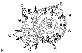
Install the transaxle housing to the transaxle case with the 16 bolts.
- Torque:
- Bolt A:
- 22 N*m{225 kgf*cm, 16 ft.*lbf}
- Bolt B:
- 29 N*m{296 kgf*cm, 21 ft.*lbf}
- Bolt C:
- 29 N*m{296 kgf*cm, 21 ft.*lbf}
- HINT:
- Apply adhesive or equivalent to bolts A and C.
- Adhesive:
- Toyota Genuine Adhesive 1344, Three Bond 1344 or equivalent
- Bolt length:
- Bolt A:
- 50 mm (1.969 in.)
- Bolt B:
- 50 mm (1.969 in.)
- Bolt C:
- 42 mm (1.654 in.)
- NOTICE:
- Apply adhesive to the bolts and tighten them within 10 minutes of application.
| 60. INSPECT INPUT SHAFT END PLAY |
Using a dial indicator, measure the input shaft end play.
- End play:
- 0.262 to 1.244 mm (0.01 to 0.049 in.)
| 61. FIX AUTOMATIC TRANSAXLE ASSEMBLY |
Fix the transaxle assembly.
| 62. INSTALL MANUAL VALVE LEVER SHAFT OIL SEAL |
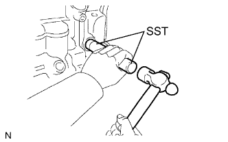
Coat a new oil seal with MP grease.
Using SST, install the oil seal to the transaxle case.
- SST
- 09950-60010(09951-00230)
09950-70010(09951-07100)
- Oil seal drive in depth:
- -0.5 to 0.5 mm (-0.0197 to 0.0197 in. )
| 63. INSTALL PARKING LOCK ROD SUB-ASSEMBLY |
Install the parking lock rod to the manual valve lever.
- HINT:
- Align the dial with the notches on the manual valve lever and turn the dial 90° to install the parking lock rod.
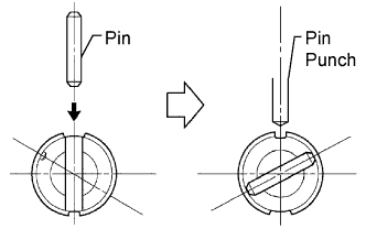
| 64. INSTALL MANUAL VALVE LEVER SUB-ASSEMBLY |
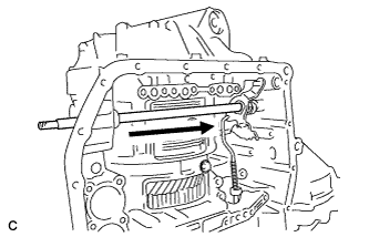
Install a new spacer and the manual valve lever shaft to the transaxle case.
- NOTICE:
- Do not damage the oil seal while installing the shaft to the transaxle case.
Using a pin punch and hammer, drive in a new pin.
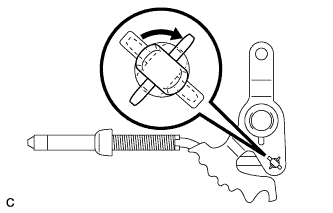
Turn the spacer and the lever shaft to align the smaller hole of the spacer with the staking position mark on the lever shaft.
Using a pin punch, stake the spacer through the small hole.
Check that the spacer does not turn.
| 65. INSTALL MANUAL VALVE LEVER SHAFT RETAINER SPRING |
Using needle-nose pliers, install the retainer spring.
- NOTICE:
- Hang the spring on the shaft securely.
| 66. INSTALL PARKING LOCK PAWL BRACKET |
Install the parking lock pawl bracket with the 2 bolts.
- Torque:
- 20 N*m{205 kgf*cm, 15 ft.*lbf}
- Bolt length:
- 25 mm (0.98 in.)
- NOTICE:
- Be sure the parking rod is placed between the parking pawl and the guide of the parking bracket after the parking bracket is installed.
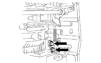
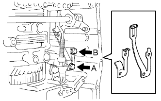
| 67. INSTALL MANUAL DETENT SPRING SUB-ASSEMBLY |
Install the manual detent spring sub-assembly with the 2 bolts.
- NOTICE:
- Make sure to install the manual detent spring and cover in this order.
- HINT:
- Tighten the bolts in the order of A and B.
- Torque:
- Bolt A:
- 20 N*m{205 kgf*cm, 15 ft.*lbf}
- Bolt B:
- 12 N*m{120 kgf*cm, 9 ft.*lbf}
- Bolt length:
- Bolt A:
- 27 mm (1.06 in.)
- Bolt B:
- 16 mm (0.63 in.)
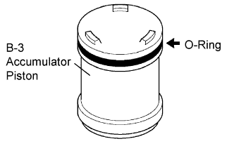
| 68. INSTALL B-3 ACCUMULATOR PISTON |
Coat a new O-ring with ATF, and install it to the B-3 accumulator piston.
- NOTICE:
- Install the O-ring to the accumulator piston not to have a twist or a pinching. Apply enough ATF to the O-ring prior to installation. Be sure about the installation position.
Coat the piston and springs with ATF, and install them to the transaxle case.
- NOTICE:
- Install the correct springs to the B-3 accumulator piston by checking the color or dimension of the springs.
Accumulator spring:Free length / Outer diameter (mm (in.))
| Color
|
Inner: 62.00 (2.4409) / 15.50 (0.610)
| Purple
|
Outer: 74.23 (2.9224) / 21.70 (0.854)
| Purple
|
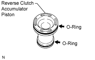
| 69. INSTALL REVERSE CLUTCH ACCUMULATOR PISTON |
Coat 2 new O-rings with ATF, and install them to the reverse clutch accumulator piston.
- NOTICE:
- Install the O-rings to the accumulator piston not to have a twist or a pinching. Apply enough ATF to the O-rings prior to installation. Be sure about the installation positions.
Coat the piston and spring with ATF, and install them to the transaxle case.
- NOTICE:
- Install the correct spring to the reverse clutch accumulator piston by checking the color or dimension of the spring.
Accumulator spring:Free length / Outer diameter (mm (in.))
| Color
|
60.96 (2.3999) / 14.10 (0.555)
| Yellow
|
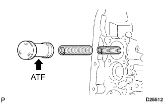
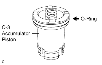
| 70. INSTALL C-3 ACCUMULATOR PISTON |
Coat a new O-ring with ATF, and install it to the C-3 accumulator piston.
- NOTICE:
- Install the O-ring to the accumulator piston not to have a twist or a pinching. Apply enough ATF to the O-ring prior to installation. Be sure about the installation position.
Coat the piston with ATF, and install it to the transaxle case.
Install the spring to the C-3 accumulator piston.
- NOTICE:
- Install the correct spring to the C-3 accumulator piston by checking the color or dimension of the spring.
Accumulator spring:Free length / Outer diameter (mm (in.))
| Color
|
72.20 (2.8425) / 19.0 (0.748)
| Colorless
|
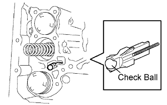
| 71. INSTALL CHECK BALL BODY |
Coat the check ball body with ATF.
Install the check ball body and spring.
- NOTICE:
- Regarding the installation of the spring for the check ball body, be sure to place the spring in the hole in the ball body. Be careful about the orientation of the parts.
| 72. INSTALL BRAKE DRUM GASKET |
Coat a new brake drum gasket with ATF, and install it to the transaxle case.
- NOTICE:
- Do not damage the lip portion of the brake drum gasket when inserting the gasket to the case. Apply enough ATF to the gasket prior to installation. Be careful about the orientation of the parts.
| 73. INSTALL TRANSAXLE CASE 2ND BRAKE GASKET |
Coat a new transaxle case 2nd brake gasket with ATF, and install it to the transaxle case.
- NOTICE:
- Do not damage the lip portion of the transaxle case 2nd brake gasket when inserting the gasket to the case. Apply enough ATF to the gasket prior to installation. Be careful about the orientation of the parts.
| 74. INSTALL NO. 1 GOVERNOR APPLY GASKET |
Coat a new No. 1 governor apply gasket with ATF, and install it to the transaxle case.
- NOTICE:
- Do not damage the lip portion of the No. 1 governor apply gasket when inserting the gasket to the case. Apply enough ATF to the gasket prior to installation. Be careful about the orientation of the parts.
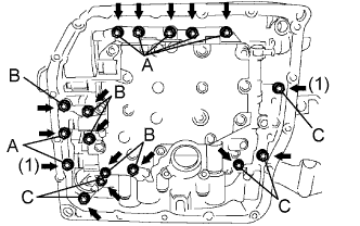
| 75. INSTALL TRANSMISSION VALVE BODY ASSEMBLY |
Check the manual valve lever position. Install the valve body to the transaxle case with the 17 bolts.
- Torque:
- 11 N*m{110 kgf*cm, 8 ft.*lbf}
- Bolt length:
- Bolt A:
- 25 mm (0.984 in.)
- Bolt B:
- 57 mm (2.244 in.)
- Bolt C:
- 41 mm (1.614 in.)
- NOTICE:
- Push the valve body against the accumulator piston spring and the check ball body to install it.
- When installing the valve body to the transaxle case, do not hold the solenoids.
- Temporarily tighten the bolts marked by (1) in the illustration first because they are positioning bolts.
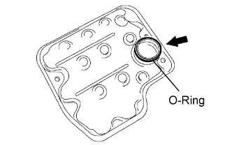
| 76. INSTALL VALVE BODY OIL STRAINER ASSEMBLY |
Coat a new O-ring with ATF, and install it to the oil strainer.
- NOTICE:
- Install the O-ring carefully not to have a twist or a pinching. Apply enough ATF to the O-ring prior to installation.
Install the oil strainer to the valve body with the 3 bolts.
- Torque:
- 11 N*m{110 kgf*cm, 8 ft.*lbf}
- NOTICE:
- Apply ATF to the bolts prior to installation.
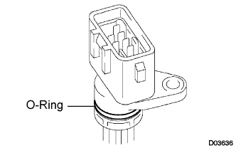
| 77. INSTALL TRANSMISSION WIRE |
Coat a new O-ring with ATF, and install it to the transmission wire.
- NOTICE:
- Install the O-ring not to have a twist or pinching. Apply enough ATF to the O-ring prior to installation.
Install the transmission wire retaining bolt.
- Torque:
- 5.4 N*m{55 kgf*cm, 48 in.*lbf}
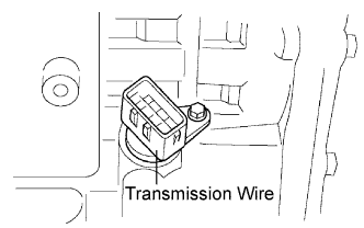
| 78. CONNECT TRANSMISSION WIRE |
Coat an O-ring of the ATF temperature sensor with ATF.
Install the ATF temperature sensor with the lock plate and bolt.
- Torque:
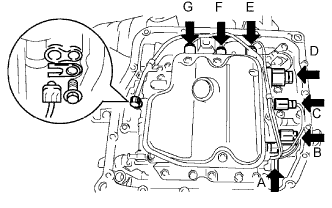
- 6.6 N*m{67 kgf*cm, 58 in.*lbf}
Connect the 7 solenoid connectors.
- NOTICE:
- Connect the connectors to A, B, C, D, E, F and G, starting with the shorter ones.
- Apply ATF to the bolt prior to installation.
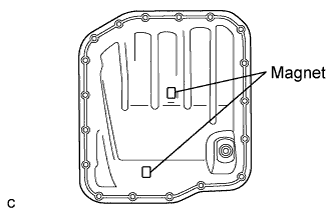
| 79. INSTALL AUTOMATIC TRANSAXLE OIL PAN SUB-ASSEMBLY |
Install the 2 magnets in the oil pan.
Apply adhesive or equivalent to the 18 bolts.
- Adhesive:
- Toyota Genuine Adhesive 1344, Three Bond 1344 or equivalent
Install a new oil pan gasket and the oil pan to the transaxle case with the 18 bolts.
- Torque:
- 7.8 N*m{80 kgf*cm, 69 in.*lbf}
- NOTICE:
- Apply adhesive to the bolts and tighten them within 10 minutes of application.
- Remove any oil or grease from the contact surface of the transaxle case and the oil pan with the gasket completely before installing the oil pan to the case.
Install a new gasket to the drain plug.
Install the drain plug.
- Torque:
- 49 N*m{500 kgf*cm, 36 ft.*lbf}
| 80. INSTALL NO. 1 TRANSAXLE CASE PLUG |
Coat 4 new O-rings with ATF, and install them to the 4 No. 1 transaxle case plugs.
Install the 4 No. 1 transaxle case plugs to the transaxle case.
- Torque:
- 7.4 N*m{75 kgf*cm, 65 in.*lbf}
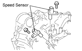
Apply liquid sealer to the "A" bolt threads.
- Adhesive:
- Toyota Genuine Adhesive 1344, Three Bond 1344 or equivalent
Install the 2 sensors to the transaxle case with the 2 bolts.
- Torque:
- 8.8 N*m{90 kgf*cm, 78 in.*lbf}
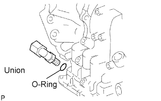
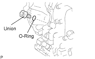
| 82. INSTALL OIL COOLER TUBE UNION (OUTLET OIL COOLER UNION) |
Coat a new O-ring with ATF, and install it to the union.
Install the union to the transaxle case.
- Torque:
- 27 N*m{276 kgf*cm, 20 ft.*lbf}
| 83. INSTALL OIL COOLER TUBE UNION (INLET OIL COOLER UNION) |
Coat a new O-ring with ATF, and install it to the union.
Install the union to the transaxle case.
- Torque:
- 25 N*m{255 kgf*cm, 18 ft.*lbf}
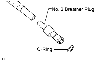
| 84. INSTALL NO. 2 BREATHER PLUG |
Coat a new O-ring with ATF.
Install the hose and a new O-ring to the breather plug.
Install the No. 2 breather plug hose to the transaxle case.
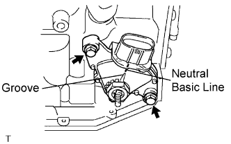
| 85. INSTALL PARK/NEUTRAL POSITION SWITCH ASSEMBLY |
Install the park/neutral position switch onto the manual valve lever shaft and temporarily install the 2 adjusting bolts.
Install a new nut stopper and nut.
- Torque:
- 6.9 N*m{70 kgf*cm, 61 in.*lbf}
Temporarily install the control shaft lever.
Turn the lever counterclockwise until it stops, and then turn it clockwise 2 notches.
Remove the control shaft lever.
Align the groove with the neutral basic line.
Hold the switch in position and tighten the 2 bolts.
- Torque:
- 5.4 N*m{55 kgf*cm, 48 in.*lbf}
Using a screwdriver, stake the nut with the nut stopper.
Install the control shaft lever, washer and nut.
- Torque:
- 13 N*m{130 kgf*cm, 9 ft.*lbf}