Transmission. Camry. Acv40 Gsv40
U250E Automatic Transaxle. Camry. Acv40 Gsv40
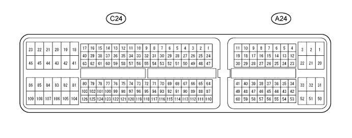
Automatic Transaxle System -- Terminals Of Ecm |
| ECM |
- HINT:
- Each ECM terminal's standard voltage is shown in the table below.
- In the table, first follow the information under "Condition". Look under "Symbols (Terminal No.)" for the terminals to inspected. The standard voltage between the terminals is shown under "Specific Condition".
- Use the illustration above as a reference for the ECM terminals.
| Symbols (Terminals No.) | Wiring Color | Terminal Description | Condition | Specified Condition |
| D (C24-56) - E1 (C24-104) | G - W-B | D shift position switch signal | Ignition switch to the ON position and shift lever D and 4 position | 10 to 14 V |
| Ignition switch to the ON position and shift lever except D and 4 position | Below 1 V | |||
| R (C24-53) - E1 (C24-104) | P - W-B | R shift position switch signal | Ignition switch to the ON position and shift lever R position | 10 to 14 V |
| Ignition switch to the ON position and shift lever except R position | Below 1 V | |||
| SPD (A24-8) - E1 (C24-104) | V - W-B | Speed signal | Vehicle speed 20 km/h (12mph) | Pulse generation (See waveform 8) |
| STP (A24-36) - E1 (C24-104) | W - W-B | Stop light switch signal | Brake pedal is depressed | 7.5 to 14 V |
| Brake pedal is released | Below 1.5 V | |||
| 4 (A24-25) - E1 (C24-104) | G - W-B | 4 shift position switch signal | Ignition switch to the ON position and shift lever 4 position | 10 to 14 V |
| Ignition switch to the ON position and shift lever except 4 position | Below 1 V | |||
| 3 (A24-26) - E1 (C24-104) | G - W-B | 3 shift position switch signal | Ignition switch to the ON position and shift lever 3 position | 10 to 14 V |
| Ignition switch to the ON position and shift lever except 3 position | Below 1 V | |||
| 2 (C24-55) - E1 (C24-104) | V - W-B | 2 shift position switch signal | Ignition switch to the ON position and shift lever 2 and L position | 10 to 14 V |
| Ignition switch to the ON position and shift lever except 2 and L position | Below 1 V | |||
| L (C24-74) - E1 (C24-104) | BR - W-B | L shift position switch signal | Ignition switch to the ON position and shift lever L position | 10 to 14 V |
| Ignition switch to the ON position and shift lever except L position | Below 1 V | |||
| P (C24-73) - E1 (C24-104) | GR - W-B | Park position switch signal | Ignition switch to the ON position and shift lever P position | 10 to 14 V |
| Ignition switch to the ON position and shift lever except P position | Below 1 V | |||
| N (C24-54) - E1 (C24-104) | SB - W-B | Neutral position switch signal | Ignition switch to the ON position and shift lever N position | 10 to 14 V |
| Ignition switch to the ON position and shift lever except N position | Below 1 V | |||
| NSW (C24-52) - E1 (C24-104) | SB - W-B | Park neutral switch signal | Ignition switch to the ON position and shift lever P and N position | Below 2 V |
| Ignition switch to the ON position and shift lever except P and N position | 10 to 14 V | |||
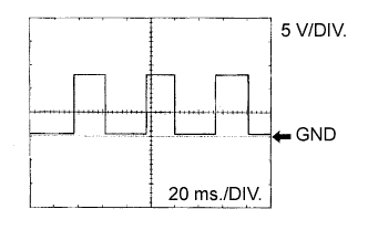
| DSL (C24-79) - E1 (C24-104) | BR - W-B | DSL solenoid signal | Vehicle speed 65 km/h (40mph), lock-up (ON to OFF) | Pulse generation (See waveform 2) |
| SR (C24-80) - E1 (C24-104) | G - W-B | SR solenoid signal | Ignition switch to the ON position | Below 1 V |
| 3rd, 4th or 5th gear | 10 to 14 V | |||
| 1st or 2nd gear | Below 1 V | |||
| S4 (C24-78) - E1 (C24-104) | GR - W-B | S4 solenoid signal | Ignition switch to the ON position | Below 1 V |
| 5th gear | 10 to 14 V | |||
| Except 5th gear | Below 1 V | |||
| SL3+ (C24-60) - SL3- (C24-61) | O - Y | SL3 solenoid signal | Engine idle speed | Pulse generation (See waveform 3) |
| SL2+ (C24-58) - SL2- (C24-59) | G - R | SL2 solenoid signal | Engine idle speed | Pulse generation (See waveform 4) |
| SL1+ (C24-57) - SL1- (C24-77) | L - L-G | SL1 solenoid signal | Engine idle speed | Pulse generation (See waveform 5) |
| NC+ (C24-101) - NC- (C24-102) | LG - P | Speed sensor (NC) signal | Vehicle speed 30 km/h (19mph): (3rd gear) Engine speed 1,400 rpm | Pulse generation (See waveform 6) |
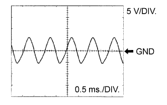
| NT+ (C24-125) - NT- (C24-124) | G - W | Speed sensor (NT) signal | Vehicle speed 20 km/h (12mph) | Pulse generation (See waveform 7) |
| SLT+ (C24-76) - SLT- (C24-75) | L - W | SLT solenoid signal | Engine idle speed | Pulse generation (See waveform 1) |
| THO1 (C24-72) - ETHO (C24-95) | Y - BR | ATF temperature sensor signal | ATF temperature: 115°C (239°F) or more | Below 1.5 V |
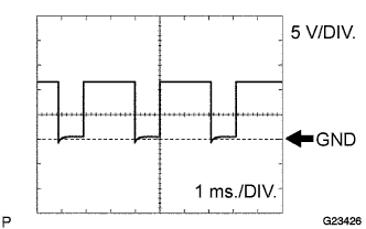
Waveform 1
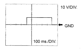
Reference: Terminal SLT+ - SLT- Tool setting 5 V/DIV., 1ms./DIV. Vehicle condition Engine idle speed Waveform 2
Reference: Terminal DSL - E1 Tool setting 10 V/DIV., 100ms./DIV. Vehicle condition Vehicle speed 65 km/h (40 mph), lock-up (ON to OFF) Waveform 3
Reference: Terminal SL3+ - SL3- Tool setting 5 V/DIV., 1ms./DIV. Vehicle condition Engine idle speed Waveform 4
Reference: Terminal SL2+ - SL2- Tool setting 5 V/DIV., 1ms./DIV. Vehicle condition Engine idle speed Waveform 5
Reference: Terminal SL1+ - SL1- Tool setting 5 V/DIV., 1ms./DIV. Vehicle condition Engine idle speed Waveform 6
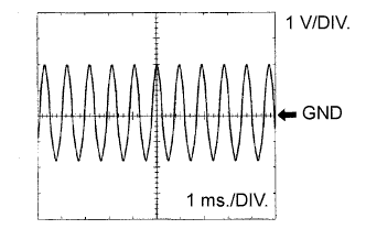
Reference: Terminal NC+ - NC- Tool setting 1 V/DIV., 1ms./DIV. Vehicle condition Vehicle speed 30 km/h (19 mph): (3rd gear)
Engine speed 1.400 rpmWaveform 7
Reference: Terminal NT+ - NT- Tool setting 5 V/DIV., 0.5ms./DIV. Vehicle condition Vehicle speed 20 km/h (12 mph) Waveform 8
Reference: Terminal SPD - E1 Tool setting 5 V/DIV., 20ms./DIV. Vehicle condition Vehicle speed 20 km/h (12 mph) - HINT:
- Depending on the vehicle, the output waveform voltage, influenced by optionally installed systems, may become 5V.
 |
 |
|
|
|
 |
 |
 |