Entry And Start System Power Source Mode Does Not Change To On (Ig)
DESCRIPTION
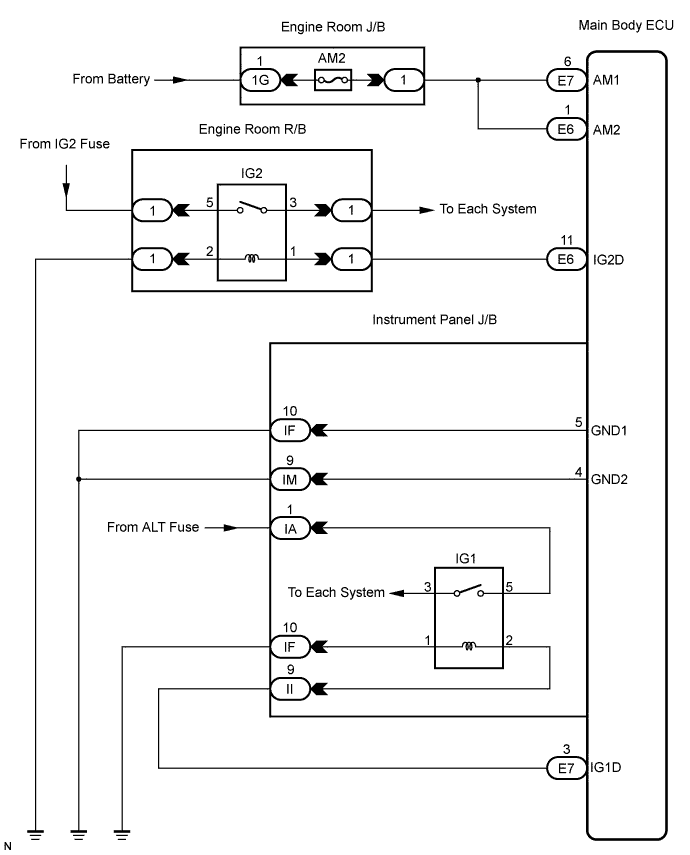
WIRING DIAGRAM
INSPECTION PROCEDURE
INSPECT FUSE (AM2)
CHECK CONNECTORS
CHECK HARNESS AND CONNECTOR (MAIN BODY ECU - BATTERY)
CHECK HARNESS AND CONNECTOR (MAIN BODY ECU - BODY GROUND)
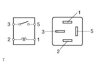
INSPECT RELAY (IG2 RELAY)
CHECK HARNESS AND CONNECTOR (ENGINE ROOM R/B - MAIN BODY ECU AND BODY GROUND)
INSPECT RELAY (IG1 RELAY)
CHECK HARNESS AND CONNECTOR (INSTRUMENT PANEL J/B - MAIN BODY ECU)
CHECK HARNESS AND CONNECTOR (INSTRUMENT PANEL J/B - BATTERY AND BODY GROUND)
INSPECT INSTRUMENT PANEL J/B
ENTRY AND START SYSTEM - Power Source Mode does not Change to ON (IG) |
DESCRIPTION
When the engine switch is pushed with the electrical key in the cabin, the main body ECU receives signals to switch the power source mode.- HINT:
- To allow use of the intelligent tester to inspect the push-button start function when the engine switch is off, repeat opening and closing any of the doors. Opening and closing a door establishes communication between the intelligent tester and the main body ECU. (Opening and closing a door can also be simulated by operating a door courtesy light switch.)
WIRING DIAGRAM
INSPECTION PROCEDURE
Remove the AM2 fuse from the engine room J/B.
Measure the resistance of the fuse.
- Standard Resistance:
Tester Connection
| Condition
| Specified Condition
|
AM2 fuse
| Always
| Below 1 Ω
|
Check that the connectors are securely connected and the terminals are not deformed or loose.
- OK:
- The connectors are securely connected and the terminals are not deformed or loose.
| | REPAIR OR REPLACE CONNECTORS |
|
|
| 3.CHECK HARNESS AND CONNECTOR (MAIN BODY ECU - BATTERY) |
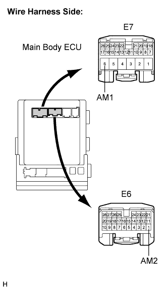
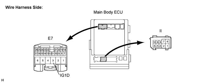
Disconnect the E6 and E7 ECU connectors.
Measure the voltage according to the value(s) in the table below.
- Standard Voltage:
Tester Connection
| Condition
| Specified Condition
|
E7-6 (AM1) - Body ground
| Always
| 11 to 14 V
|
E6-1 (AM2) - Body ground
| Always
| 11 to 14 V
|
| | REPAIR OR REPLACE HARNESS OR CONNECTOR |
|
|
| 4.CHECK HARNESS AND CONNECTOR (MAIN BODY ECU - BODY GROUND) |
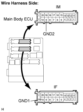
Disconnect the IF and IM ECU connectors.
Measure the resistance according to the value(s) in the table below.
- Standard Resistance:
Tester Connection
| Condition
| Specified Condition
|
IF-10 (GND1) - Body ground
| Always
| Below 1 Ω
|
IM-9 (GND2) - Body ground
| Always
| Below 1 Ω
|
| | REPAIR OR REPLACE HARNESS OR CONNECTOR |
|
|
| 5.INSPECT RELAY (IG2 RELAY) |
Remove the IG2 relay from the engine room R/B.
Measure the resistance according to the value(s) in the table below.
- Standard Resistance:
Tester Connection
| Condition
| Specified Condition
|
3 - 5
| When battery voltage is not applied to terminals 1 and 2
| 10 kΩ or higher
|
3 - 5
| When battery voltage is applied to terminals 1 and 2
| Below 1 Ω
|
| | REPLACE RELAY (IG1 RELAY) |
|
|
| 6.CHECK HARNESS AND CONNECTOR (ENGINE ROOM R/B - MAIN BODY ECU AND BODY GROUND) |
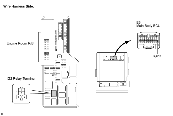
Remove the IG2 relay from the engine room R/B.
Disconnect the E6 ECU connector.
Measure the resistance according to the value(s) in the table below.
- Standard Resistance:
Tester Connection
| Condition
| Specified Condition
|
Engine room R/B IG2 relay terminal 1 - E6-11 (IG2D)
| Always
| Below 1 Ω
|
Engine room R/B IG2 relay terminal 2 - Body ground
| Always
| Below 1 Ω
|
E6-11 (IG2D) - Body ground
| Always
| 10 kΩ or higher
|
| | REPAIR OR REPLACE HARNESS OR CONNECTOR |
|
|
| 7.INSPECT RELAY (IG1 RELAY) |
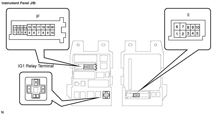
Remove the IG1 relay from the instrument panel J/B.
Measure the resistance according to the value(s) in the table below.
- Standard Resistance:
Tester Connection
| Condition
| Specified Condition
|
3 - 5
| When battery voltage is not applied to terminals 1 and 2
| 10 kΩ or higher
|
3 - 5
| When battery voltage is applied to terminals 1 and 2
| Below 1 Ω
|
| | REPLACE RELAY (IG1 RELAY) |
|
|
| 8.CHECK HARNESS AND CONNECTOR (INSTRUMENT PANEL J/B - MAIN BODY ECU) |
Disconnect the Il J/B connector.
Disconnect the E7 ECU connector.
Measure the resistance according to the value(s) in the table below.
- Standard Resistance:
Tester Connection
| Condition
| Specified Condition
|
II-9 - E7-3 (IG1D)
| Always
| Below 1 Ω
|
E7-3 (IG1D) - Body ground
| Always
| 10 kΩ or higher
|
| | REPAIR OR REPLACE HARNESS OR CONNECTOR |
|
|
| 9.CHECK HARNESS AND CONNECTOR (INSTRUMENT PANEL J/B - BATTERY AND BODY GROUND) |
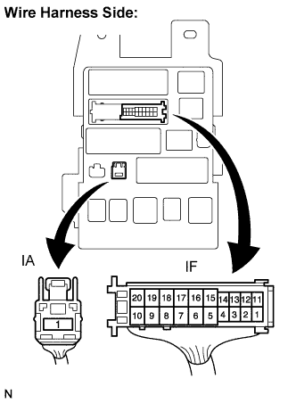
Disconnect the IF and IA J/B connectors.
Measure the resistance according to the value(s) in the table below.
- Standard Resistance:
Tester Connection
| Condition
| Specified Condition
|
IF-10 - Body ground
| Always
| Below 1 Ω
|
Measure the voltage according to the value(s) in the table below.
- Standard Voltage:
Tester Connection
| Condition
| Specified Condition
|
IA-1 - Body ground
| Always
| 11 to 14 V
|
| | REPAIR OR REPLACE HARNESS OR CONNECTOR |
|
|
| 10.INSPECT INSTRUMENT PANEL J/B |
Measure the resistance according to the value(s) in the table below.
- Standard Resistance:
Tester Connection
| Condition
| Specified Condition
|
IF-10 - IG1 relay terminal-1
| Always
| Below 1 Ω
|
II-9 - IG1 relay terminal-2
| Always
| Below 1 Ω
|
IF-10 - Body ground
| Always
| 10 kΩ or higher
|
II-9 - Body ground
| Always
| 10 kΩ or higher
|
| NG |
|
|
|
| REPLACE INSTRUMENT PANEL J/B |
|