Dtc B2275 Stsw Monitor Malfunction
DESCRIPTION
WIRING DIAGRAM
INSPECTION PROCEDURE
CHECK DTC OUTPUT
CHECK WIRE HARNESS (MAIN BODY ECU - ECM)
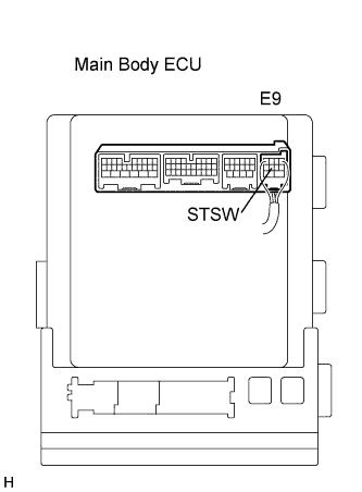
INSPECT MAIN BODY ECU
CHECK MAIN BODY ECU OPERATION
DTC B2275 STSW Monitor Malfunction |
DESCRIPTION
This DTC is output when there is an open, short, or any other problem in the engine start request output circuit inside the main body ECU or in the external circuit.- HINT:
- When the main body ECU is replaced with a new one and the negative (-) battery terminal is connected, the power source mode becomes the IG-ON mode. When the battery is removed and reinstalled, the power source mode that was selected when the battery was removed is restored.
- After the main body ECU is replaced, perform the registration procedures for the engine immobiliser system.
DTC No.
| DTC Detection Condition
| Trouble Area
|
B2275
| ST output circuit (engine starting request signal circuit) inside main body ECU or other related circuit is malfunctioning
| - Main body ECU
- ECM
- Wire harness or connector
|
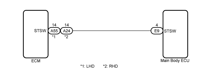
WIRING DIAGRAM
INSPECTION PROCEDURE
Clear the DTCs (CAMRY_ACV40 RM000000YEH05QX.html).
- HINT:
- After all DTCs are cleared, turn the engine switch on (IG) and depress the brake pedal. After 15 seconds have elapsed, check if the trouble occurs again.
Check for DTCs again.
- OK:
- DTC is not output.
| 2.CHECK WIRE HARNESS (MAIN BODY ECU - ECM) |
Disconnect the E9 ECU connector.
Disconnect the A55*1 or E24*2 ECM connector.
Measure the resistance according to the value(s) in the table below.
- Standard Resistance:
Tester Connection
| Condition
| Specified Condition
|
E9-4 (STSW) - A55-14 (STSW)*1
E9-4 (STSW) - A24-14 (STSW)*2
| Always
| Below 1 Ω
|
E9-4 (STSW) - Body ground
| Always
| 10 kΩ or higher
|
- *1: for LHD
- *2: for RHD
| | REPAIR OR REPLACE HARNESS OR CONNECTOR |
|
|
Reconnect the connectors.
Measure the voltage according to the value(s) in the table below.
- Standard Voltage:
Tester Connection
| Condition
| Specified Condition
|
E9-4 (STSW) - Body ground
| Brake pedal depressed, Engine switch hold on (ST)
| Output voltage at terminal AM1 or AM2 is -2 V or more.
|
| 4.CHECK MAIN BODY ECU OPERATION |
After replacing the main body ECU with a normally functioning ECU, check that the engine can start.
- OK:
- Engine can start normally.
| | GO TO ENGINE CONTROL SYSTEM |
|
|
| OK |
|
|
|
| END (MAIN BODY ECU WAS DEFECTIVE) |
|