Oil Pump -- Removal |
| 1. REMOVE ENGINE ASSEMBLY WITH TRANSAXLE |
| 2. SECURE ENGINE |
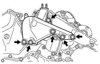
| 3. REMOVE INTAKE AIR SURGE TANK ASSEMBLY |
Disconnect the 2 water by-pass hoses from the throttle body assembly (*1).
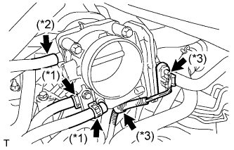 |
Disconnect the vapor feed hose (*2).
Disconnect the throttle body assembly connector and clamp (*3).
Disconnect the No. 1 ventilation hose.
Remove the bolt and vacuum hose clamp.
 |
Disconnect the connector.
 |
Remove the 4 bolts, No. 1 surge tank stay and throttle body bracket.
Using a 5 mm socket hexagon wrench, remove the 4 bolts (*4).
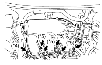 |
Remove the 2 nuts and intake air surge tank (*5).
Remove the gasket from the intake air surge tank.
| 4. REMOVE IGNITION COIL ASSEMBLY |
Remove the 6 bolts and 6 ignition coils.
| 5. REMOVE NO. 2 ENGINE MOUNTING STAY RH |
Remove the bolt and No. 2 engine mounting stay RH.
| 6. REMOVE EXHAUST MANIFOLD SUB-ASSEMBLY RH |
Disconnect the A/F sensor connector clamp.
Uniformly loosen and remove the 6 nuts.
 |
Remove the manifold and gasket.
| 7. REMOVE OIL LEVEL GAUGE GUIDE SUB-ASSEMBLY |
Remove the oil level gauge.
 |
Remove the 2 bolts, oil level gauge guides No. 1 and No. 2.
Remove the O-rings from the oil level gauge guide.
| 8. REMOVE NO. 2 MANIFOLD STAY |
Remove the bolt, nut and No. 2 manifold stay.
 |
| 9. REMOVE NO. 2 EXHAUST MANIFOLD HEAT INSULATOR |
Remove the 3 bolts and No. 2 insulator.
 |
| 10. REMOVE EXHAUST MANIFOLD SUB-ASSEMBLY LH |
Uniformly loosen and remove the 6 nuts.
 |
Remove the manifold and gasket.
| 11. REMOVE ENGINE MOUNTING BRACKET RH |
Remove the 3 bolts and engine mounting bracket RH.
 |
| 12. REMOVE V-RIBBED BELT TENSIONER ASSEMBLY |
Remove the 5 bolts and V-ribbed belt tensioner assembly.
 |
| 13. REMOVE NO. 2 TIMING GEAR COVER |
Remove the 2 bolts and No. 2 timing gear cover.
 |
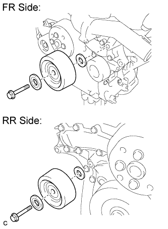
| 14. REMOVE NO. 2 IDLER PULLEY SUB-ASSEMBLY |
Remove the bolt, 2 plates and No. 2 idler pulley sub-assembly.
- HINT:
- Plate diameter:
- Idler pulley cover plate: 33.6 mm (1.32 in.)
- No. 2 idler pulley cover plate: 37.8 mm (1.49 in.)
 |
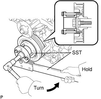
| 15. REMOVE WATER PUMP PULLEY |
Using SST, hold the water pump pulley.
- SST
- 09960-10010(09962-01000,09963-00700)
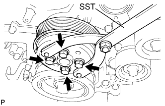 |
Remove the 4 bolts and water pump pulley.
| 16. REMOVE RADIO SETTING CONDENSER |
Remove the 2 bolts and 2 radio setting condensers.
 |
| 17. REMOVE NO. 1 VACUUM SWITCHING VALVE ASSEMBLY |
Remove the bolt and No. 1 vacuum switching valve.
 |
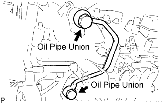
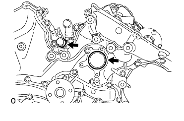
| 18. REMOVE NO. 1 OIL PIPE |
Remove the 2 oil pipe unions and oil pipe.
 |
Remove the oil control valve filter LH and gaskets.
| 19. REMOVE OIL PIPE |
Remove the bolt.
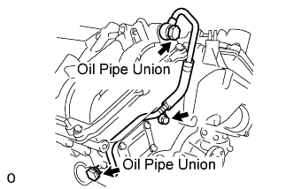 |
Remove the 2 oil pipe unions and oil pipe.
Remove the oil control valve filter RH and gaskets.
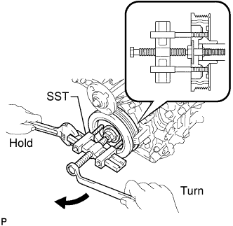
| 20. REMOVE CRANKSHAFT PULLEY |
Using SST, loosen the crankshaft pulley bolt.
- SST
- 09213-70011(09213-70020)
09330-00021
 |
Using SST, remove the crankshaft pulley bolt and crankshaft pulley.
- SST
- 09950-50013(09951-05010,09952-05010,09953-05020,09954-05021)
 |
| 21. REMOVE NO. 1 ENGINE MOUNTING BRACKET FRONT LH |
Remove the 6 bolts and engine mounting bracket.
 |
Using "Torx" socket wrench E8, remove the 2 stud bolts.
| 22. REMOVE WATER INLET HOUSING |
Remove the 2 nuts, water inlet and thermostat.
 |
Remove the gasket.
Remove the housing plug.
Remove the housing drain cock.
Remove the 2 stud bolts.
Separate the water by-pass hose No. 1.
Remove the 2 bolts, nut, and water inlet housing.
 |
Remove the 2 O-rings.
 |
| 23. REMOVE CYLINDER HEAD COVER SUB-ASSEMBLY (for Bank 1) |
Remove the 12 bolts, seal washer, head cover and gasket.
 |
Remove the 3 gaskets.
 |
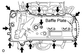
| 24. REMOVE CYLINDER HEAD COVER SUB-ASSEMBLY (for Bank 2) |
Remove the 12 bolts, seal washer, head cover and gasket.
- NOTICE:
- The baffle plate is located on the back of the portion shown in the illustration. Do not damage the baffle plate when removing the head cover.
 |
Remove the 3 gaskets.
 |
| 25. REMOVE NO. 2 OIL PAN SUB-ASSEMBLY |
Remove the 16 bolts and 2 nuts.
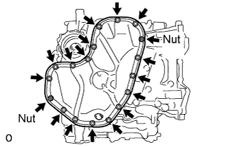 |
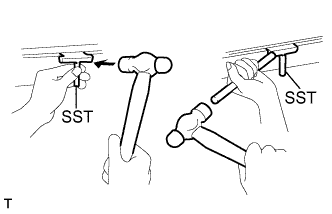
Insert the blade of SST between the oil pans. Cut through the applied sealer and remove the No. 2 oil pan sub-assembly.
- SST
- 09032-00100
- NOTICE:
- Be careful not to damage the contact surfaces of the oil pans.
 |
Using "Torx" socket wrench E6, remove the 2 stud bolts.
| 26. REMOVE OIL STRAINER SUB-ASSEMBLY |
Remove the bolt, 2 nuts, oil strainer and gasket.
 |
Using "Torx" socket wrench E6, remove the 2 stud bolts.
| 27. REMOVE OIL PAN SUB-ASSEMBLY |
Remove the 16 bolts and 2 nuts.
- HINT:
- Be sure to clean the bolts and stud bolts and check the threads for cracks or other damage.
 |
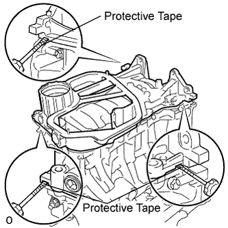
Remove the oil pan by prying between the oil pan and cylinder block with a screwdriver.
- NOTICE:
- Be careful not to damage the contact surfaces of the cylinder block and oil pan.
- HINT:
- Tape the screwdriver tip before use.
 |
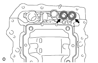
Remove the 2 O-rings.
 |
Using "Torx" socket wrench E8, remove the 2 stud bolts.
| 28. REMOVE TIMING CHAIN COVER SUB-ASSEMBLY |
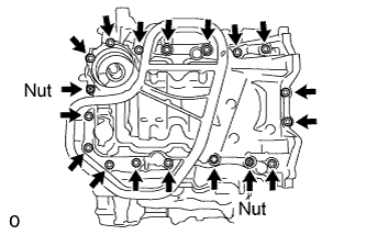
Remove the 23 bolts and 2 nuts as shown in the illustration.
 |
Remove the timing chain cover by prying between the timing chain cover and cylinder head or cylinder block with a screwdriver.
- NOTICE:
- Be careful not to damage the contact surfaces of the cylinder head, cylinder block and chain cover.
- HINT:
- Tape the screwdriver tip before use.
 |
Remove the gasket.
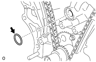 |
| 29. REMOVE TIMING CHAIN CASE OIL SEAL |
Using a screwdriver, pry out the oil seal.
- HINT:
- Tape the screwdriver tip before use.
 |