Fuel Injector -- Removal |
| 1. DISCHARGE FUEL SYSTEM PRESSURE |
- HINT:
| 2. DISCONNECT CABLE FROM NEGATIVE BATTERY TERMINAL |
| 3. DRAIN ENGINE COOLANT |
- NOTICE:
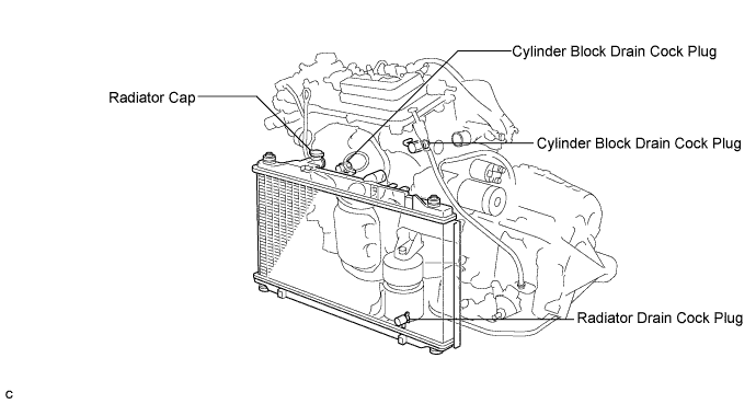
- Do not remove the radiator cap sub-assembly while the engine and radiator are still hot. Pressurized, hot engine coolant and steam may be released and cause serious burns.
Remove the radiator cap sub-assembly from the radiator assembly.
Loosen the radiator drain cock plug and 2 cylinder block drain cock plugs, then drain the coolant.
- HINT:
- Collect the coolant in a container and dispose of it according to the regulations in your area.
| 4. REMOVE FRONT WIPER ARM AND BLADE ASSEMBLY LH |
Remove the nut and the front wiper arm and blade assembly LH.
 |
| 5. REMOVE FRONT WIPER ARM AND BLADE ASSEMBLY RH |
Remove the nut and the front wiper arm and blade assembly RH.
 |
| 6. REMOVE FRONT FENDER TO COWL SIDE SEAL LH |
Disengage the claw and remove the front fender to cowl side seal LH.
 |
| 7. REMOVE FRONT FENDER TO COWL SIDE SEAL RH |
Disengage the claw and remove the front fender to cowl side seal RH.
 |
| 8. REMOVE COWL TOP VENTILATOR LOUVER SUB-ASSEMBLY |
Remove the 2 clips.
 |
Disengage the 4 claws and remove the cowl top ventilator louver sub-assembly.
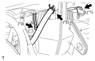
| 9. REMOVE WINDSHIELD WIPER MOTOR AND LINK ASSEMBLY |
Disconnect the connector.
 |
Remove the 4 bolts and the windshield wiper motor and link assembly.
 |
| 10. REMOVE COWL TOP PANEL OUTER SUB-ASSEMBLY |
Remove the 4 bolts, 4 nuts and cowl top panel outer sub-assembly.
 |
| 11. REMOVE V-BANK COVER SUB-ASSEMBLY |
Hold the front of the V-bank cover and raise it to disengage the 2 retainers on the front of the cover. Continue to raise the cover to disengage the retainer on the rear of the cover and remove the cover.
- NOTICE:
- Attempting to disengage both front and rear clips at the same time may cause the cover to break.
 |
| 12. REMOVE AIR CLEANER CAP SUB-ASSEMBLY |
Disconnect the 3 vacuum hoses.
 |
Disconnect the mass air flow meter connector (*1).
 |
Disconnect the No. 2 ventilation hose (*2).
Disconnect the hose band (*3).
Disconnect the 3 bands, and remove the air cleaner cap sub-assembly.
 |
| 13. REMOVE INTAKE AIR SURGE TANK ASSEMBLY |
Disconnect the 2 water by-pass hoses from the throttle with motor body assembly. (*1)
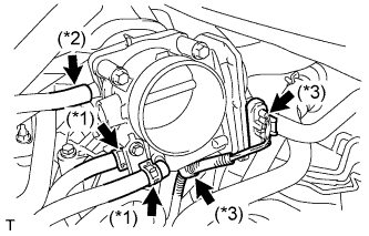 |
Disconnect the vapor feed hose. (*2)
Disconnect the throttle with motor body assembly connector and clamp. (*3)
Disconnect the No. 1 ventilation hose. (*4)
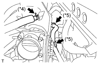 |
Disconnect the union to check valve hose. (*5)
Remove the bolt and vacuum hose clamp.
 |
Disconnect the connector.
 |
Using a 5 mm socket hexagon wrench, remove the 4 bolts. (*1)
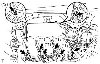 |
Remove the 2 nuts, 2 bolts and intake air surge tank. (*2)
Remove the gasket from the intake air surge tank.
| 14. DISCONNECT FUEL TUBE SUB-ASSEMBLY |
Remove the No. 2 fuel pipe clamp.
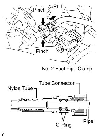 |
Pinch the tube connector and then pull out the fuel pipe.
- NOTICE:
- Check that there is no dirt or other foreign objects around the connector before this operation and clean the connector as necessary.
- It is necessary to prevent mud or dirt from entering the quick connector. If mud enters the connector, the O-rings may not seal properly.
- Remove the quick connector by hand.
- Do not bend or twist the nylon tube. Protect the connector by covering it with a plastic bag.
- If the pipe and the connector are stuck, try wiggling or pushing and pulling the connector to release it and pull the connector off of the pipe carefully.
| 15. REMOVE FUEL INJECTOR ASSEMBLY |
Disconnect the 6 fuel injector connectors.
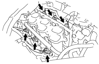 |
Remove the 5 bolts and fuel delivery pipe together with the 6 fuel injectors.
- NOTICE:
- Be careful not to drop the fuel injectors when removing the fuel delivery pipe.
 |
Remove the 6 insulators from the intake manifold.
 |
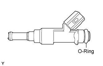
Pull out the fuel injectors from the fuel delivery pipe.
 |
Remove the 6 O-rings from the injectors.
 |