Engine Unit -- Reassembly |
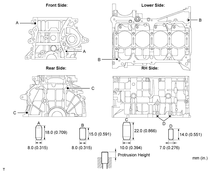
| 1. INSTALL RING PIN |
Using a plastic hammer, tap into the ring pin.
- Standard protrusion:
Item Protrusion Pin A 6 mm (0.236 in.) Pin B 5 mm (0.197 in.)
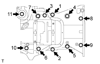
| 2. INSTALL STUD BOLT |
Install the stud bolts as shown in the illustration.
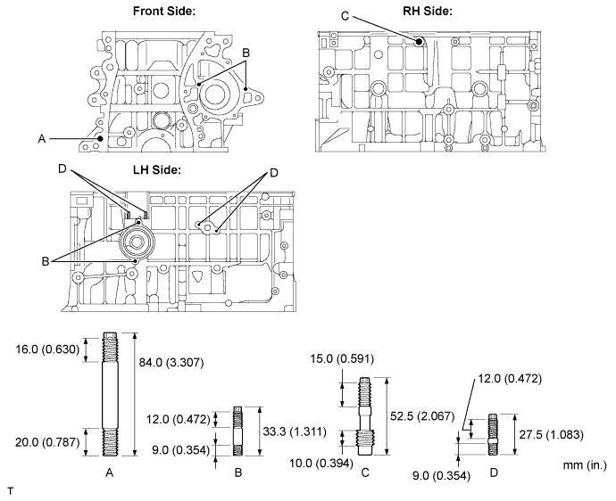
- Torque:
- Stud Bolt A:
- 22 N*m{220 kgf*cm, 16 ft.*lbf}
- Stud Bolt B:
- 5.0 N*m{51 kgf*cm, 44 in.*lbf}
- Stud Bolt C:
- 9.5 N*m{97 kgf*cm, 84 in.*lbf}
- Stud Bolt D:
- 5.0 N*m{51 kgf*cm, 44 in.*lbf}
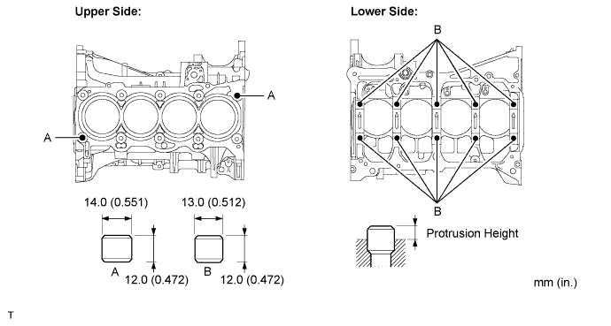
| 3. INSTALL STRAIGHT PIN |
Using a plastic hammer, tap into the straight pin.
- Standard protrusion:
Item Protrusion Pin A 8 mm (0.315 in.) Pin B 7.5 mm (0.295 in.) Pin C 12 mm (0.472 in.) Pin D 5 mm (0.197 in.)
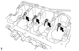
| 4. INSTALL NO. 1 OIL NOZZLE SUB-ASSEMBLY |
Using a 5 mm hexagon wrench, install the oil nozzles with the bolts.
- Torque:
- 7.0 N*m{71 kgf*cm, 62 in.*lbf}
 |
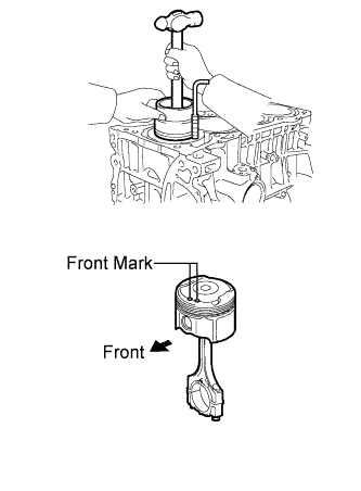
| 5. INSTALL PISTON |
Using a screwdriver, install a new snap ring at one end of the piston pin hole.
- HINT:
- Make sure that the end gap of the snap ring is not aligned with the pin hole cutout portion of the piston.
 |
Gradually heat the piston to approximately 80 to 90°C (176 to 194°F).
Align the front marks of the piston and connecting rod, and push in the piston with your thumb.
 |
Using a screwdriver, install a new snap ring on the other end of the piston pin hole.
- HINT:
- Make sure that the end gap of the snap ring is not aligned with the pin hole cutout portion of the piston.
Check the fitting condition between the piston and piston pin by trying to move the piston back and forth on the piston pin.
 |
| 6. INSTALL PISTON RING SET |
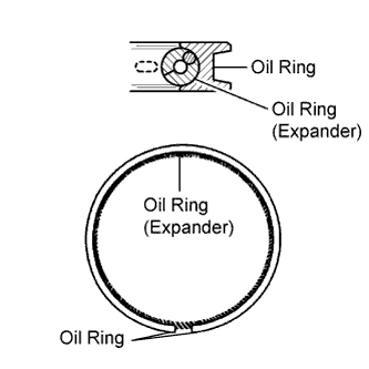
Install the oil ring expander and oil ring rail by hand.
- NOTICE:
- Install the expander and oil ring so that their ring ends are at opposite sides.
- Securely install the expander to the inner groove of the oil ring.
 |
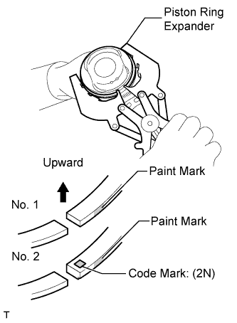
Using a piston ring expander, install the 2 compression rings so that the paint marks are positioned as shown in the illustration.
- NOTICE:
- Install the compression ring No. 2 with the code mark (2N) facing upward.
 |
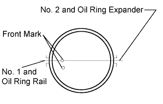
Position the piston rings so that the ring ends are as shown in the illustration.
 |
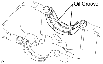
| 7. INSTALL CRANKSHAFT BEARING |
Install the upper bearing with an oil groove on the cylinder block.
- NOTICE:
- Do not apply engine oil to the bearings and the contact surfaces.
 |
| 8. INSTALL NO. 2 CRANKSHAFT BEARING |
Install the lower bearing on the bearing cap.
- NOTICE:
- Clean the backside of the bearing and the bearing surface of the connecting rod. The surface should be free of dust and oils.
 |
| 9. INSTALL UPPER CRANKSHAFT THRUST WASHER |
Install the 2 thrust washers under the No. 3 journal of the cylinder block with the oil grooves facing outward.
 |
Apply engine oil to the crankshaft thrust washer.
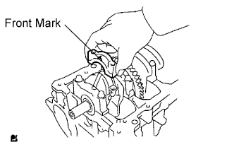
| 10. INSTALL CRANKSHAFT |
Apply engine oil to the upper bearing and install the crankshaft on the cylinder block.
Apply engine oil to the lower bearing.
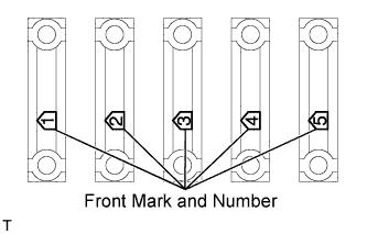
Examine the front marks and install the bearing caps on the cylinder block.
 |
Apply a light coat of engine oil to the threads and under the bearing cap bolts.
Install the crankshaft bearing cap bolts.
- NOTICE:
- The main bearing cap bolts are tightened in 2 progressive steps.
Step 1
Install and uniformly tighten the 10 main bearing cap bolts in the sequence shown in the illustration.
- Torque:
- 20 N*m{204 kgf*cm, 15 ft.*lbf}
Retighten the 10 main bearing cap bolts in the sequence shown in the illustration.
- Torque:
- 40 N*m{408 kgf*cm, 30 ft.*lbf}
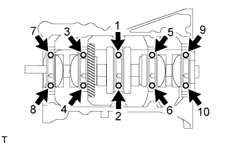
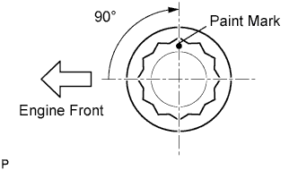
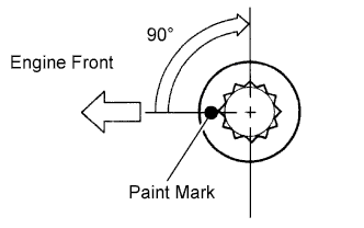
Step 2
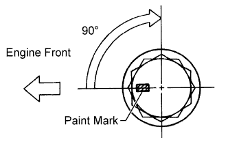
Mark the front of the bearing cap bolts with paint.
Retighten the bearing cap bolts by 90°in the numerical order shown in the illustration.

Check that the paint mark is now at a 90°angle to the front.
Check that the crankshaft turns smoothly.
Check the crankshaft thrust clearance (CAMRY_ACV40 RM0000026TQ02EX_01_0045.html).
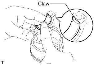
| 11. INSTALL CONNECTING ROD BEARING |
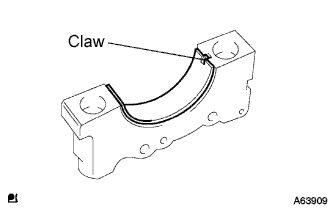
Align the bearing claw with the groove of the connecting rod or connecting cap.
- NOTICE:
- Do not apply engine oil to the bearings and the contact surfaces.
 |
| 12. INSTALL PISTON SUB-ASSEMBLY WITH CONNECTING ROD |
- NOTICE:
- The connecting rod cap bolts are tightened in 2 progressive steps.
Apply engine oil to the cylinder walls, the pistons, and the surfaces of connecting rod bearings.
Check the position of the piston ring ends.
|
Using a piston ring compressor, push the correctly numbered piston and connecting rod assemblies into each cylinder with the front mark of the piston facing forward.
- NOTICE:
- Match the numbered connecting rod cap with the connecting rod.
 |
Check that the protrusion of the connecting rod cap is facing in the correct direction.
 |
Apply a light coat of engine oil to the threads and under the heads of the connecting rod cap bolts.
Install the connecting cap bolts.
- NOTICE:
- The connecting cap bolts should be tightened in 2 progressive steps.
Step 1
Install and alternately tighten the bolts of the connecting rod cap in several steps.
- Torque:
- 25 N*m{250 kgf*cm, 18 ft.*lbf}

Step 2
Mark the front of the connecting rod cap bolts with paint.
Retighten the cap bolts by 90°as shown in the illustration.
Check that the crankshaft turns smoothly.
Check the connecting rod thrust clearance (CAMRY_ACV40 RM0000026TQ02EX_01_0043.html).
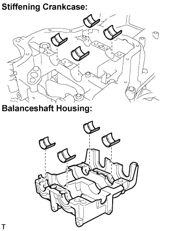
| 13. INSTALL NO. 1 BALANCESHAFT BEARING |
Install the bearings in the crankcase and balanceshaft housing.
- NOTICE:
- Do not apply engine oil to the bearings and the contact surfaces.
 |
Apply a light coat of engine oil to the bearings.
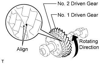
| 14. INSTALL NO. 1 AND NO. 2 BALANCESHAFT SUB-ASSEMBLY |
Rotate the driven gear No. 1 of balanceshaft No. 1 in the rotating direction until it hits the stopper.
- NOTICE:
- Confirm that the matchmarks on driven gears No. 1 and No. 2 are matched.
 |
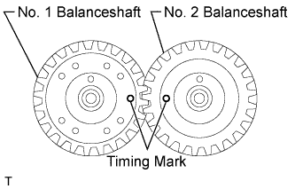
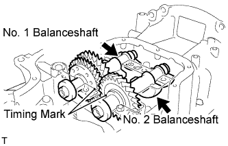
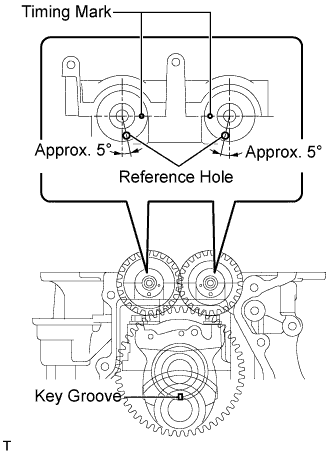
Align the timing marks of the No. 1 and No. 2 balanceshafts as shown in the illustration.
 |
Place the No. 1 and No. 2 balanceshafts on the crankcase.
 |
Apply a light coat of engine oil under the heads of the balanceshaft housing bolts.
Install the balanceshaft housing bolts.
- NOTICE:
- The balance shaft housing bolts are tightened in 2 progressive steps.
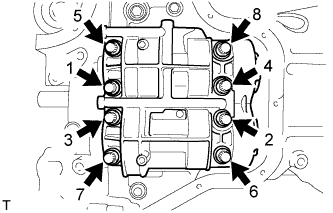
Step 1
Install and uniformly tighten the 8 bolts in the sequence shown in the illustration.
- Torque:
- 22 N*m{220 kgf*cm, 16 ft.*lbf}
Step 2
Mark the front side of each balanceshaft housing bolt head with paint.
Retighten the bolts by 90°as shown in the illustration.
Check that the paint marks are now at a 90°angle to the front.
| 15. INSTALL STIFFENING CRANKCASE ASSEMBLY |
Place a new O-ring on the cylinder block, as shown in the illustration.
 |
Temporarily tighten the pulley set bolt.
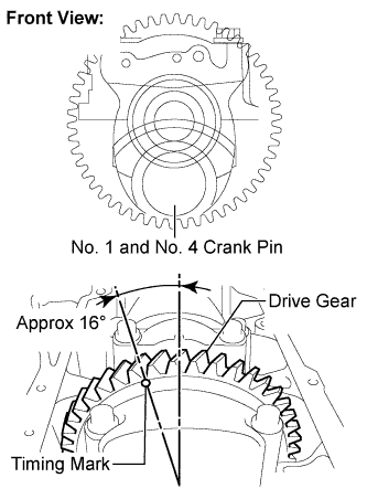
Turn the crankshaft to set the crank pins of the No. 1 and No. 4 cylinders to the bottom.
- HINT:
- Make sure that the timing mark on the balanceshaft drive gear is positioned as shown in the illustration.
 |
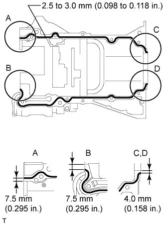
Apply seal packing in a continuous bead (diameter: 2.5 to 3.0 mm (0.098 to 0.118 in.)) to the places shown in the illustration.
- Seal packing:
- Toyota Genuine Seal Packing Black, Three bond 1207B or Equivalent
- NOTICE:
- Remove any oil from the contact surface.
- Install the crankcase within 3 minutes after applying seal packing.
- Do not start the engine for at least 2 hours after installing the crankcase stiffener.
 |
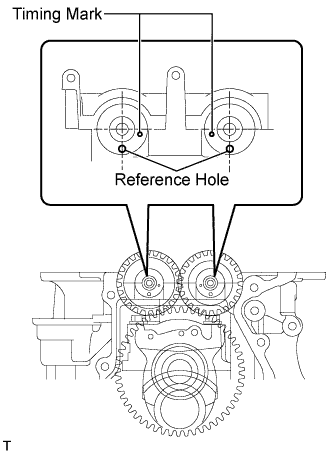
Install the stiffening crankcase so that the reference holes on the balanceshafts are positioned as shown in the illustration.
 |
Temporarily install the crankcase with the 11 bolts.
- Bolt length:
Item Length Bolt A 122 mm (4.803 in.) Bolt B 45 mm (1.772 in.)
 |
Uniformly tighten the 11 bolts in the sequence shown in the illustration.
- Torque:
- 24 N*m{245 kgf*cm, 18 ft.*lbf}
 |
Wipe off the excess seal packing with a clean piece of cloth.
Turn the crankshaft again to set the key groove to the bottom. Make sure that the timing marks are aligned as shown in the illustration.
- HINT:
- An '○' is stamped as a timing mark.
 |
Remove the pulley set bolt.
| 16. INSTALL OIL PUMP ASSEMBLY |
Install a new gasket and oil pump with the 3 bolts.
- Torque:
- 19 N*m{194 kgf*cm, 14 ft.*lbf}
 |
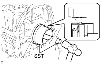
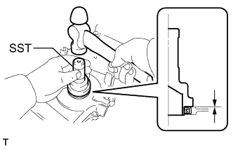
| 17. INSTALL ENGINE REAR OIL SEAL |
Using SST and a hammer, evenly tap the oil seal until its surface is flush with the rear oil seal retainer edge.
- SST
- 09223-15030
09950-70010(09951-07100)
- NOTICE:
- Keep the lip free from foreign materials.
 |
Apply MP grease to a new oil seal lip.
- NOTICE:
- Wipe off extra grease on the crankshaft.
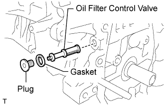
| 18. INSTALL OIL CONTROL VALVE FILTER |
Check that no foreign matter is on the mesh part of the filter.
Using an 8 mm socket hexagon wrench, install a new gasket and the oil control valve filter with the screw plug.
- Torque:
- 30 N*m{306 kgf*cm, 22 ft.*lbf}
- NOTICE:
- Do not touch the mesh when installing the oil control valve filter.
 |
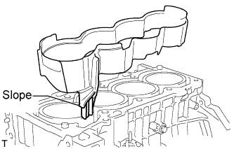
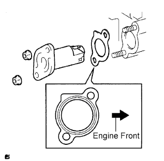
| 19. INSTALL CYLINDER BLOCK WATER JACKET SPACER |
Install the water jacket spacer as shown in the illustration.
- HINT:
- Be sure to face the slope to the front of the engine.
 |
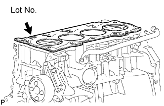
| 20. INSTALL CYLINDER HEAD GASKET |
Place a new gasket on the cylinder block surface with the Lot No. stamp facing upward.
- NOTICE:
- Remove any oil from the contact surface.
- Make sure that the gasket is installed in the correct direction.
 |
| 21. INSTALL CYLINDER HEAD SUB-ASSEMBLY |
- HINT:
- The cylinder head bolts are tightened in 2 progressive steps.
Apply a light coat of engine oil to the bolt threads and the area beneath the bolt heads that come in contact with the washers.
Install the bolts and plate washers to the cylinder head.
- NOTICE:
- Do not drop the washers into the cylinder head.
Using several steps, uniformly install and tighten the 10 cylinder head set bolts and plate washers with a 10 mm bi-hexagon wrench in the order shown in the illustration.
- Torque:
- 70 N*m{714 kgf*cm, 52 ft.*lbf}
 |
Mark the front side of the cylinder head bolt with paint.
 |
Retighten the cylinder head bolts 90° in the sequence shown in the illustration.
Check that the paint mark is now at a 90° angle to the front.
| 22. INSTALL CAMSHAFT TIMING OIL CONTROL VALVE ASSEMBLY |
Apply a light coat of engine oil to a new O-ring, then install it onto the camshaft timing oil control valve.
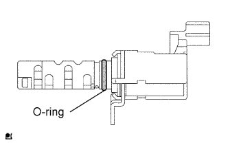 |
Install the camshaft timing oil control valve with the bolt.
- Torque:
- 9.0 N*m{92 kgf*cm, 80 in.*lbf}
 |
| 23. INSTALL CAMSHAFT TIMING GEAR ASSEMBLY |
Put the camshaft timing gear and camshaft together with the straight pin and key groove misaligned, as shown in the illustration.
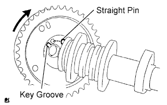 |
Turn the camshaft timing gear as shown in the illustration while pushing it gently against the camshaft. Push further at the position where the pin fits into the groove.
- NOTICE:
- Be sure not to turn the camshaft timing gear to the retard angle side (the right angle).
Check that there is no clearance between the gear and camshaft.
Tighten the flange bolt with the camshaft timing gear fixed in place.
- Torque:
- 54 N*m{551 kgf*cm, 40 ft.*lbf}
Check that the camshaft timing gear can move to the retard angle side (the right direction) and is locked in the most retarded position.
| 24. INSTALL CAMSHAFT TIMING SPROCKET |
Clamp the camshaft in a vise.
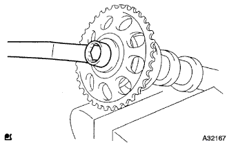 |
Tighten the flange bolt with the camshaft timing sprocket fixed.
- Torque:
- 54 N*m{551 kgf*cm, 40 ft.*lbf}
| 25. INSTALL NO. 1 CAMSHAFT BEARING |
Install the No. 1 camshaft bearing.
 |
| 26. INSTALL NO. 2 CAMSHAFT BEARING |
Install the No. 2 camshaft bearing.
 |
| 27. INSTALL CAMSHAFT |
Apply a light coat of engine oil to the journal portion of the camshaft.
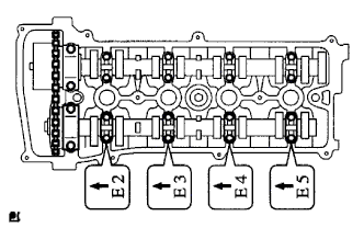
Examine the front marks and numbers, and check that the order is as shown in the illustration. Then install the bearing caps into the cylinder head.
 |
Apply a light coat of engine oil to the threads and under the heads of the bearing cap bolts.
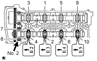
Using several steps, uniformly tighten the 10 bearing cap bolts in the sequence shown in the illustration.
- Torque:
- No. 1 Bearing cap:
- 30 N*m{301 kgf*cm, 22 ft.*lbf}
- No. 3 Bearing cap:
- 9.0 N*m{92 kgf*cm, 80 in.*lbf}
 |
| 28. INSTALL NO. 2 CAMSHAFT |
Apply a light coat of engine oil to the journal portion of the No. 2 camshaft.
Examine the front marks and numbers, and check that the order is as shown in the illustration. Then install the bearing caps onto the cylinder head.
 |
Apply a light coat of engine oil to the threads and under the heads of the bearing cap bolts.
Using several steps, uniformly tighten the 10 bearing cap bolts in the sequence shown in the illustration.
- Torque:
- No. 1 Bearing cap:
- 30 N*m{301 kgf*cm, 22 ft.*lbf}
- No. 3 Bearing cap:
- 9.0 N*m{92 kgf*cm, 80 in.*lbf}
 |
| 29. INSTALL KEYS |
Install the 2 keys.
 |
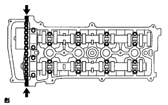
| 30. INSTALL NO. 2 CHAIN SUB-ASSEMBLY |
Set the crankshaft key into the left horizontal position.
 |
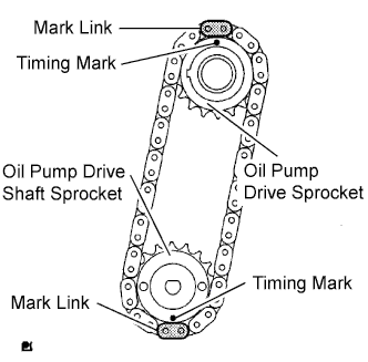
Turn the drive shaft so that the cutout faces upward.
Align the yellow mark links with the timing marks of each gear as shown in the illustration.
 |
Install the sprockets onto the crankshaft and oil pump shaft with the chain wrapped on the gears.
Temporarily tighten the oil pump drive shaft sprocket with the nut.
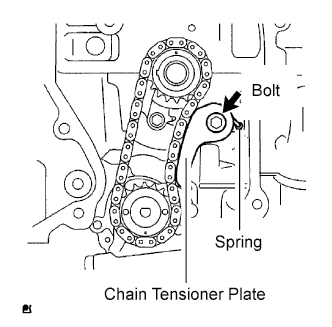
Insert the damper spring into the adjusting hole, and then install the chain tensioner plate with the bolt.
- Torque:
- 12 N*m{122 kgf*cm, 9 ft.*lbf}
 |
Align the adjusting hole of the oil pump drive shaft sprocket with the groove of the oil pump.
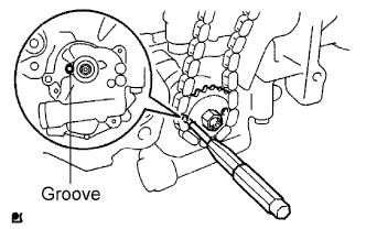 |
Insert a 4 mm diameter bar into the adjusting hole of the oil pump drive shaft gear to lock the gear in position, and then tighten the nut.
- Torque:
- 30 N*m{301 kgf*cm, 22 ft.*lbf}
Rotate the crankshaft clockwise by 90°, and align the crankshaft key to the top.
 |
| 31. INSTALL CRANKSHAFT TIMING SPROCKET |
Install the crankshaft timing sprocket.
 |
| 32. INSTALL NO. 1 CHAIN VIBRATION DAMPER |
Install the chain vibration damper with the 2 bolts.
- Torque:
- 9.0 N*m{92 kgf*cm, 80 in.*lbf}
 |
| 33. INSTALL CHAIN SUB-ASSEMBLY |
Set the No. 1 cylinder to TDC/compression.
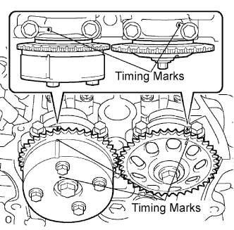
Turn the camshafts with a wrench (using the hexagonal lobe) to align the timing marks of the camshaft timing gear with each timing mark located on the No. 1 and No. 2 bearing caps as shown in the illustration.
Using the crankshaft pulley bolt, turn the crankshaft to position with the key on the crankshaft upward.

 |
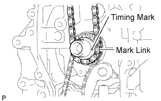
Install the chain onto the crankshaft timing sprocket with the gold or pink mark link aligned with the timing mark on the crankshaft.
 |
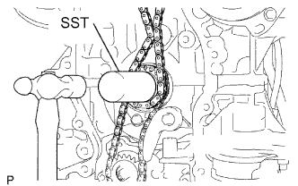
Using SST and a hammer, tap in the crankshaft timing sprocket.
- SST
- 09309-37010
 |
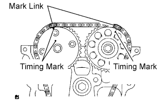
Align the gold or yellow link with each timing mark located on the camshaft timing gear and sprocket, then install the chain.
 |
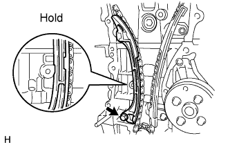
| 34. INSTALL CHAIN TENSIONER SLIPPER |
Install the chain tensioner slipper with the bolt.
- Torque:
- 19 N*m{194 kgf*cm, 14 ft.*lbf}
 |
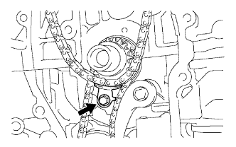
| 35. INSTALL TIMING CHAIN GUIDE |
Install the timing chain guide with the bolt.
- Torque:
- 9.0 N*m{92 kgf*cm, 80 in.*lbf}
 |
| 36. INSTALL NO. 1 CRANKSHAFT POSITION SENSOR PLATE |
Install the sensor plate with the "F" mark facing forward.
 |
| 37. INSTALL TIMING CHAIN CASE OIL SEAL |
Using SST, tap in a new oil seal until its surface is flush with the timing chain cover edge.
- SST
- 09223-22010
 |
Apply a light coat of MP grease to the lip of the oil seal.
- NOTICE:
- Keep the gap between the timing chain cover edge and the oil seal free of foreign matter.
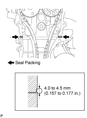
| 38. INSTALL TIMING CHAIN COVER SUB-ASSEMBLY |
Remove any old packing (FIPG) material and be careful not to drop any oil on the contact surfaces of the timing chain cover, cylinder head and cylinder block.
Apply seal packing (diameter: 4.0 to 4.5 mm (0.157 to 0.177 in.)) as shown in the illustration.
- Seal packing:
- Toyota Genuine Seal Packing Black, Three Bond 1207B or Equivalent
 |
Apply seal packing in a continuous bead as shown in the illustration.
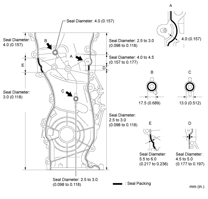
- Seal packing:
- Toyota Genuine Seal Packing Black, Three Bond 1207B or Equivalent
- NOTICE:
- Remove any oil from the contact surface.
- Install the chain cover within 3 minutes after applying seal packing.
- Do not start the engine for at least 2 hours after installing.
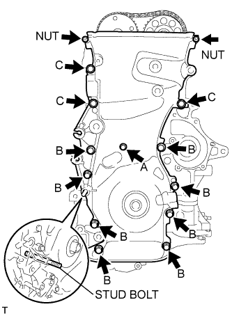
Install the timing chain cover with the 12 bolts and 2 nuts.
- Torque:
- Bolt A:
- 9.0 N*m{92 kgf*cm, 80 in.*lbf}
- Bolt B:
- 25 N*m{255 kgf*cm, 18 ft.*lbf}
- Bolt C:
- 55 N*m{561 kgf*cm, 41 ft.*lbf}
- Nut:
- 11 N*m{112 kgf*cm, 8 ft.*lbf}
Bolt length Item Length Bolt A 30 mm (1.18 in.) length for 10 mm head Bolt B 30 mm (1.18 in.) length for 12 mm head Bolt C 40 mm (1.57 in.) length for 14 mm head
 |
Using a E10 "torx" socket, install the stud bolt to the drive belt tensioner.
- Torque:
- 22 N*m{220 kgf*cm, 16 ft.*lbf}
| 39. INSTALL V-RIBBED BELT TENSIONER ASSEMBLY |
Install the V-ribbed belt tensioner with the bolt and nut.
- Torque:
- 60 N*m{607 kgf*cm, 44 ft.*lbf}
- NOTICE:
- Do not lift the engine more than necessary.
 |
| 40. INSTALL OIL PAN SUB-ASSEMBLY |
Remove any old packing material and be careful not to drop any oil on the contact surfaces of the cylinder block and oil pan.
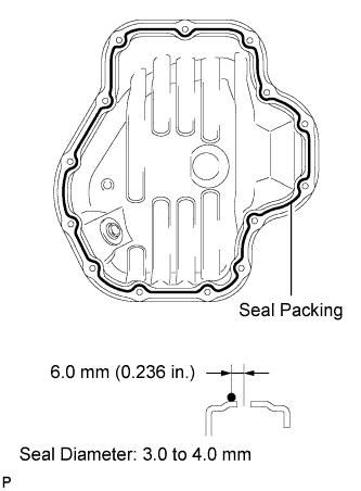 |
Apply a continuous bead of seal packing (Diameter 3.0 to 4.0 mm (0.118 to 0.157 in.)) as shown in the illustration.
- Seal packing:
- Toyota Genuine Seal Packing Block, Three Bond 1207B or Equivalent
- NOTICE:
- Remove any oil from the contact surfaces.
- Install the oil pan within 3 minutes after applying seal packing.
- Do not start the engine for at least 2 hours after installing.
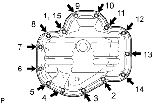
Install the oil pan to the cylinder block.
Uniformly tighten the 12 bolts and 2 nuts in the sequence shown in the illustration.
- Torque:
- 9.0 N*m{92 kgf*cm, 80 in.*lbf}
 |
| 41. INSTALL OIL PAN DRAIN PLUG |
Install a new gasket and oil pan drain plug with a new gasket.
- Torque:
- 25 N*m{255 kgf*cm, 18 ft.*lbf}
 |
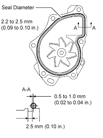
| 42. INSTALL WATER PUMP ASSEMBLY |
Remove any old seal packing material from the contact surface.
Apply a continuous line of seal packing as shown in the illustration.
- Seal packing:
- Toyota Genuine Seal Packing Black, Three Bond 1207B or Equivalent
- Standard seal diameter:
- 2.2 to 2.5 mm (0.09 to 0.10 in.)
- NOTICE:
- Remove any oil from the contact surface.
- The parts must be set within 3 minutes after applying seal packing. Otherwise, the material must be removed and reapplied.
 |
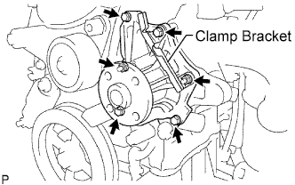
Install the water pump and clamp bracket with the 4 bolts and 2 nuts.
- Torque:
- 9.0 N*m{92 kgf*cm, 80 in.*lbf}
 |
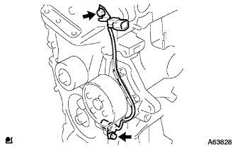
Install the wire of the crankshaft position sensor onto the clamp bracket.
 |
Install the clamp of the crankshaft position sensor onto the water pump.
| 43. INSTALL WATER PUMP PULLEY |
 |
Using SST, install the water pump pulley with the 4 bolts.
- SST
- 09960-10010(09962-01000,09963-00700)
- Torque:
- 26 N*m{265 kgf*cm, 19 ft.*lbf}
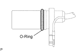
| 44. INSTALL CRANKSHAFT POSITION SENSOR |
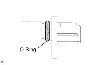
Apply a light coat of engine oil to the O-ring of the sensor.
 |
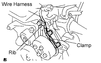
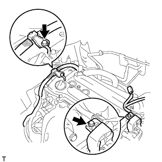
Confirm that the wire harness of the sensor is placed as shown in the illustration.
 |
Install the sensor with the 2 bolts.
- Torque:
- 9.0 N*m{92 kgf*cm, 80 in.*lbf}
 |
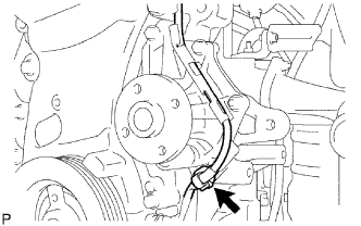
Install the clamp of the crankshaft position sensor onto the water pump.
 |
| 45. INSTALL CRANKSHAFT PULLEY |
Align the pulley set key with the key groove of the pulley.
Using SST, fix the pulley in place and tighten the bolt.
- SST
- 09213-54015(91651-60855)
09330-00021
- Torque:
- 180 N*m{1,835 kgf*cm, 133 ft.*lbf}
 |
| 46. INSTALL NO. 1 CHAIN TENSIONER ASSEMBLY |
Release the ratchet pawl, then fully push in the plunger and hook the hook to the pin so that the plunger is in the position shown in the illustration.
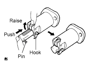 |
Install a new gasket and the chain tensioner with the 2 nuts.
- Torque:
- 9.0 N*m{92 kgf*cm, 80 in.*lbf}
- NOTICE:
- If the hook releases the plunger while the chain tensioner is being installed, set the hook again.
 |
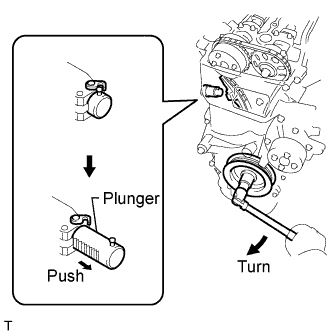
Turn the crankshaft counterclockwise, then disconnect the plunger knock pin from the hook.
 |
Turn the crankshaft clockwise, then check that the plunger is extended.
 |
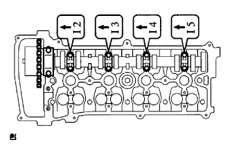
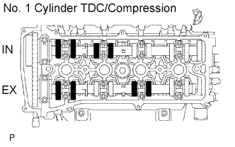
| 47. INSPECT VALVE CLEARANCE |
Check only the valves indicated.
Using a feeler gauge, measure the clearance between the valve lifter and camshaft.
- Standard valve clearance (cold):
Item Standard Condition Intake 0.19 to 0.29 mm (0.0075 to 0.0114 in.) Exhaust 0.38 to 0.48 mm (0.0150 to 0.0189 in.)
Record any out-of-specification valve clearance measurements. They will be used later to determine the required replacement valve clearance lifters.
 |
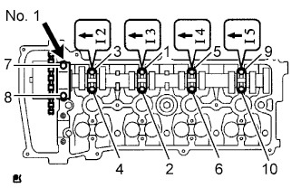
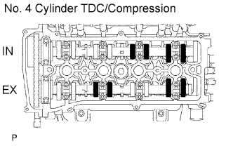
Turn the crankshaft 1 revolution (360°) and set the No. 4 cylinder to the TDC/compression.
Check only the valves indicated.
Using a feeler gauge, measure the clearance between the valve lifter and camshaft.
- Standard valve clearance (cold):
Item Standard Condition Intake 0.19 to 0.29 mm (0.0075 to 0.0114 in.) Exhaust 0.38 to 0.48 mm (0.0150 to 0.0189 in.)
Record any out-of-specification valve clearance measurements. They will be used later to determine the required replacement valve lifters.
 |
| 48. ADJUST VALVE CLEARANCE |
Remove the No. 2 camshaft (CAMRY_ACV40 RM000000YIB01BX.html).
Remove the camshaft (CAMRY_ACV40 RM000000YIB01BX.html).
Remove the valve lifters.
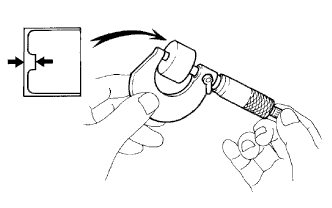
Using a micrometer, measure the thickness of the removed valve lifters.
 |
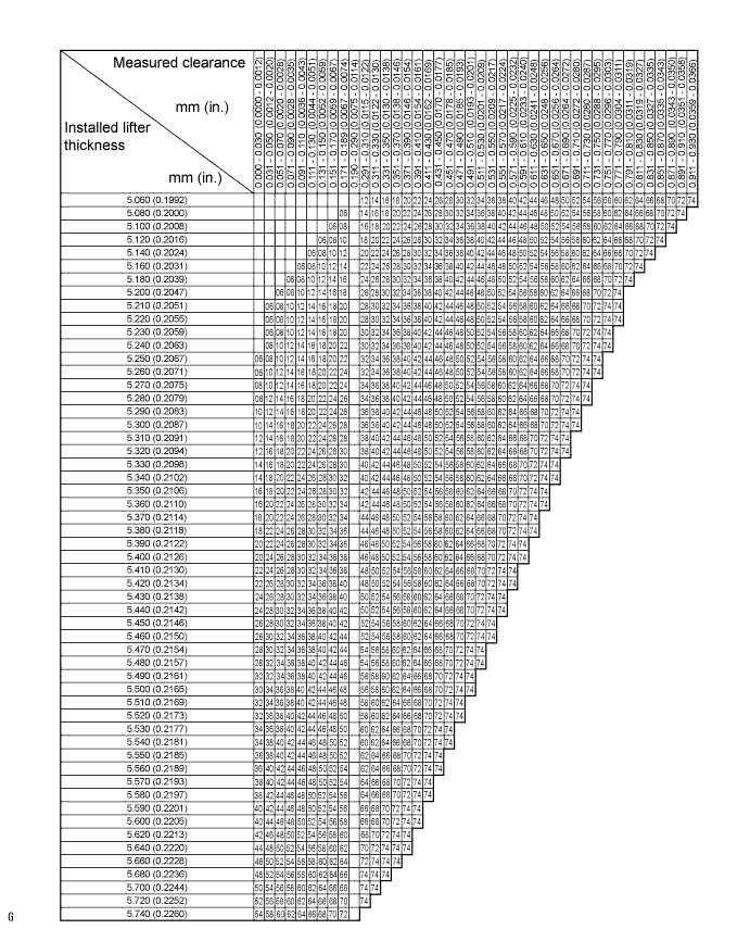
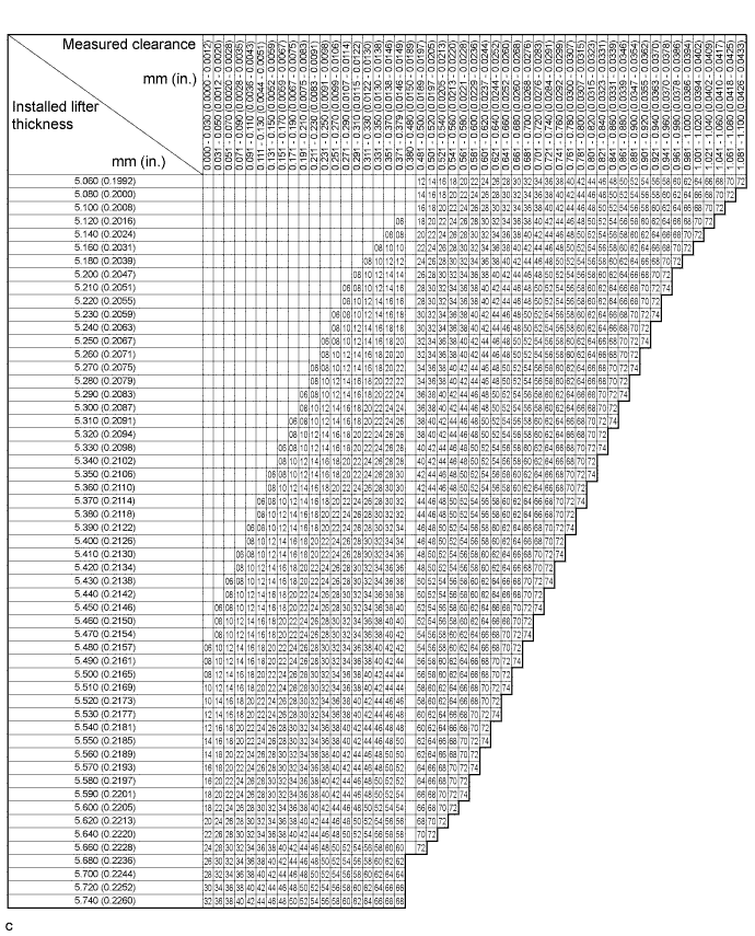
Calculate the thickness of a new lifter so that the valve clearance comes within the specified values.
- New lifter thickness:
Item Specification Intake A = B + (C - 0.24 mm (0.0095 in.)) Exhaust A = B + (C - 0.43 mm (0.0169 in.))
CALCULATION EXAMPLE (Intake):A New lifter thickness B Used lifter thickness C Measured valve clearance - Measured intake valve clearance = 0.40 mm (0.0158 in.)
(Measured - Specification = Excess clearance) - 0.40 mm (0.0158 in.) - 0.24 mm (0.0095 in.) = 0.16 mm (0.0063 in.)
- Measured used lifter measurement = 5.250 mm (0.2067 in.)
- New lifter thickness = 5.410 mm (0.2130 in.)
(Excess clearance + Used lifter thickness = Ideal new lifter) - 0.16 mm (0.0063 in.) + 5.250 mm (0.2067 in.) = 5.410 mm (0.2130 in.)
- Closest new lifter = 5.420 mm (0.2134 in.)
- Select No. 42 lifter
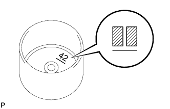
Select a new lifter with a thickness as close as possible to the calculated values.
- HINT:
- Lifters are available in 35 sizes in increments of 0.020 mm (0.0008 in.), from 5.060 to 5.740 mm (0.1992 to 0.2260 in.).
- The identification number inside the valve lifters shows the value to 2 decimal places. (The illustration shows 5.420 mm (0.2134 in.)
 |
Valve lifter selection chart (intake).
New lifter thickness Lifter No. Thickness
mm (in.)Lifter No. Thickness
mm (in.)Lifter No. Thickness
mm (in.)06 5.060 (0.1992) 30 5.300 (0.2087) 54 5.540 (0.2181) 08 5.080 (0.2000) 32 5.320 (0.2094) 56 5.560 (0.2189) 10 5.100 (0.2008) 34 5.340 (0.2102) 58 5.580 (0.2197) 12 5.120 (0.2016) 36 5.360 (0.2110) 60 5.600 (0.2205) 14 5.140 (0.2024) 38 5.380 (0.2118) 62 5.620 (0.2213) 16 5.160 (0.2031) 40 5.400 (0.2126) 64 5.640 (0.2220) 18 5.180 (0.2039) 42 5.420 (0.2134) 66 5.660 (0.2228) 20 5.200 (0.2047) 44 5.440 (0.2142) 68 5.680 (0.2236) 22 5.220 (0.2055) 46 5.460 (0.2150) 70 5.700 (0.2244) 24 5.240 (0.2063) 48 5.480 (0.2157) 72 5.720 (0.2252) 26 5.260 (0.2071) 50 5.500 (0.2165) 74 5.740 (0.2260) 28 5.280 (0.2079) 52 5.520 (0.2173) - - - Standard intake valve clearance (cold):
- 0.19 to 0.29 mm (0.0075 to 0.0114 in.)
The 5.250 mm (0.2067 in.) lifter is installed, and the measured clearance is 0.400 mm (0.0157 in.). Replace the 5.250 mm (0.2067 in.) lifter with a new No. 42 lifter.
Valve lifter selection chart (exhaust).
New lifter thickness Lifter No. Thickness
mm (in.)Lifter No. Thickness
mm (in.)Lifter No. Thickness
mm (in.)06 5.060 (0.1992) 30 5.300 (0.2087) 54 5.540 (0.2181) 08 5.080 (0.2000) 32 5.320 (0.2094) 56 5.560 (0.2189) 10 5.100 (0.2008) 34 5.340 (0.2102) 58 5.580 (0.2197) 12 5.120 (0.2016) 36 5.360 (0.2110) 60 5.600 (0.2205) 14 5.140 (0.2024) 38 5.380 (0.2118) 62 5.620 (0.2213) 16 5.160 (0.2031) 40 5.400 (0.2126) 64 5.640 (0.2220) 18 5.180 (0.2039) 42 5.420 (0.2134) 66 5.660 (0.2228) 20 5.200 (0.2047) 44 5.440 (0.2142) 68 5.680 (0.2236) 22 5.220 (0.2055) 46 5.460 (0.2150) 70 5.700 (0.2244) 24 5.240 (0.2063) 48 5.480 (0.2157) 72 5.720 (0.2252) 26 5.260 (0.2071) 50 5.500 (0.2165) 74 5.740 (0.2260) 28 5.280 (0.2079) 52 5.520 (0.2173) - - - Standard exhaust valve clearance (cold):
- 0.38 to 0.48 mm (0.0150 to 0.0189 in.)
The 5.340 mm (0.2102 in.) lifter is installed, and the measured clearance is 0.430 mm (0.0169 in.). Replace the 5.340 mm (0.2102 in.) lifter with a new No. 42 lifter.
Install the selected valve lifter.
| 49. INSTALL CAMSHAFT POSITION SENSOR |
Apply a light coat of engine oil to the O-ring of the sensor.
 |
Install the sensor with the bolt.
- Torque:
- 9.0 N*m{92 kgf*cm, 80 in.*lbf}
 |
| 50. INSTALL CYLINDER HEAD COVER GASKET |
Install the gasket to the cylinder head cover.
- NOTICE:
- Remove any oil from the contact surface.
 |
| 51. INSTALL CYLINDER HEAD COVER SUB-ASSEMBLY |
Remove any old packing material from the contact surface.
Apply seal packing to the 2 locations shown in the illustration.
- Seal packing:
- Toyota Genuine Seal Packing Block, Three Bond 1207B or Equivalent
- NOTICE:
- Remove any oil from the contact surface.
- Install the cylinder head cover within 3 minutes of applying seal packing.
- Do not add engine oil for at least 2 hours after installing the cylinder head cover.
 |
Install the cylinder head cover with the 8 bolts and 2 nuts.
- Torque:
- Bolt A:
- 11 N*m{112 kgf*cm, 8 ft.*lbf}
- Bolt B:
- 14 N*m{143 kgf*cm, 10 ft.*lbf}
- Nut:
- 11 N*m{112 kgf*cm, 8 ft.*lbf}
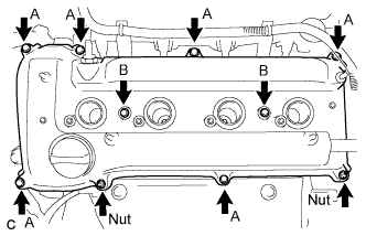 |
Install the 2 engine wires with the 2 bolts.
- Torque:
- 8.4 N*m{86 kgf*cm, 74 in.*lbf}
 |
| 52. INSTALL OIL COOLER ASSEMBLY |
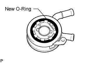
Clean the oil cooler contact surface on the cooler mounting.
Install a new O-ring to the oil cooler.
 |
Apply a light coat of engine oil to the threads and under the head of the union bolt.
Install the oil cooler with the plate washer, oil filter union and nut.
- Torque:
- Oil Filter Union:
- 79 N*m{806 kgf*cm, 58 ft.*lbf}
- Nut:
- 9.0 N*m{92 kgf*cm, 80 in.*lbf}
 |
Apply adhesive to the threads of the oil filter union.
- Adhesive:
- Toyota Genuine Adhesive 1324, Three Bond 1324 or Equivalent
Install the union bolt.
- Torque:
- 25 N*m{255 kgf*cm, 18 ft.*lbf}
 |
| 53. INSTALL OIL FILTER SUB-ASSEMBLY |
Check and clean the oil filter installation surface.
Apply clean engine oil to the gasket of a new oil filter.
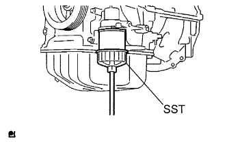
Lightly screw the oil filter into place, and tighten it until the gasket contacts the seat.
When using a torque wrench:
Using SST, tighten the oil filter.
- SST
- 09228-06501
- Torque:
- 13 N*m{133 kgf*cm, 10 ft.*lbf}
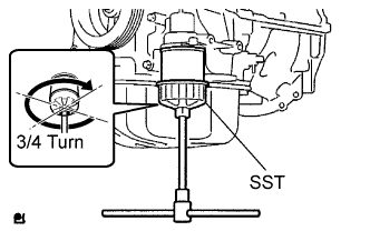
When not using a torque wrench:
Using SST, tighten it an additional 3/4 turn.
- SST
- 09228-06501
| 54. INSTALL SPARK PLUG |
Install the spark plugs.
- Torque:
- 19 N*m{194 kgf*cm, 14 ft.*lbf}
 |
| 55. INSTALL VENTILATION VALVE SUB-ASSEMBLY |
Apply adhesive to the threads of the ventilation valve.
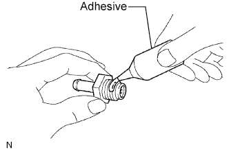 |
Install the ventilation valve.
- Torque:
- 19 N*m{194 kgf*cm, 14 ft.*lbf}
- Adhesive:
- Toyota Genuine Adhesive 1324, Three Bond 1324 or Equivalent
 |
| 56. INSTALL OIL FILLER CAP GASKET |
Install the gasket to the cap.
 |
| 57. INSTALL OIL FILLER CAP SUB-ASSEMBLY |
Install the oil filler cap.
 |