Cylinder Head -- Reassembly |
| 1. INSTALL INTAKE VALVE GUIDE BUSH |
Using a caliper gauge, measure the bush bore diameter of the cylinder head.
- Cylinder bore diameter:
- 10.285 to 10.306 mm (0.4049 to 0.4057 in.)
- Select a new guide bush (STD or O/S 0.05):
Bush size Bush bore diameter Use STD 10.285 to 10.306 mm (0.4049 to 0.4057 in.) Use O/S 0.05 10.335 to 10.356 mm (0.4069 to 0.4077 in.)
 |
Heat the cylinder head to 80 to 100°C (176 to 212°F).
Place the cylinder head on wooden blocks.
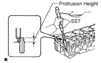
Using SST and a hammer, tap in a new guide bush to the specified protrusion height.
- SST
- 09201-10000(09201-01050)
09950-70010(09951-07100)
- Protrusion height:
- 9.6 to 10.0 mm (0.3779 to 0.3937 in.)
 |
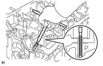
Using a sharp 5.5 mm reamer, ream the guide bush to obtain the standard specified clearance between the guide bush and valve stem.
- Standard oil clearance:
- 0.025 to 0.060 mm (0.0010 to 0.0024 in.)
 |
| 2. INSTALL EXHAUST VALVE GUIDE BUSH |
Using a caliper gauge, measure the bush bore diameter of the cylinder head.
- Diameter:
- 10.285 to 10.306 mm (0.4049 to 0.4057 in.)
- Select a new guide bush (STD or O/S 0.05):
Bush size Bush bore diameter Use STD 10.285 to 10.306 mm (0.4049 to 0.4057 in.) Use O/S 0.05 10.335 to 10.356 mm (0.4069 to 0.4077 in.)
 |
Heat the cylinder head to 80 to 100°C (176 to 212°F).
Place the cylinder head on wooden blocks.
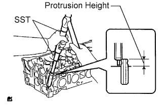
Using SST and a hammer, tap in a new guide bush to the specified protrusion height.
- SST
- 09201-10000(09201-01050)
09950-70010(09951-07100)
- Protrusion height:
- 9.6 to 10.0 mm (0.3779 to 0.3937 in.)
 |
Using a sharp 5.5 mm reamer, ream the guide bush to obtain the standard specified clearance between the guide bush and valve stem.
- Standard oil clearance:
- 0.030 to 0.065 mm (0.0012 to 0.0026 in.)
 |
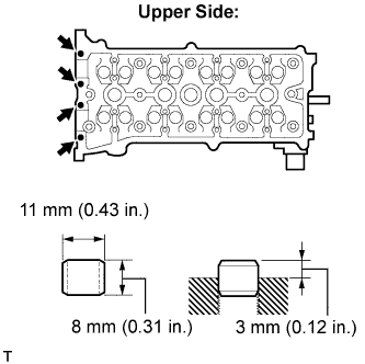
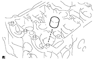
| 3. INSTALL RING W/HEAD PIN |
Using a plastic-faced hammer, tap in a new ring pin to the specified protrusion height.
- Protrusion height:
- 3 mm (0.12 in.)
 |
| 4. INSTALL STUD BOLT |
- NOTICE:
- If the stud bolt is deformed or the threads are damaged, replace it.
Using E5 and E7 "torx" sockets, install the stud bolts.
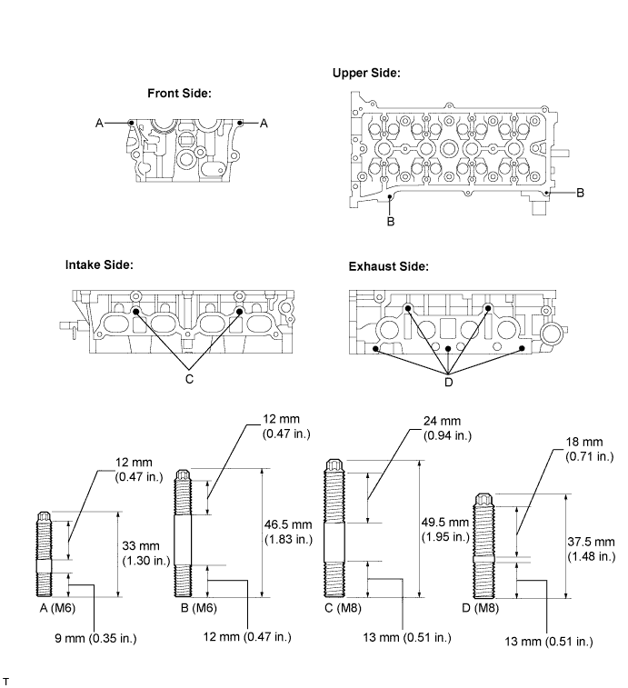
- Torque:
- Bolt A:
- 5.0 N*m{51 kgf*cm, 44 in.*lbf}
- Bolt B:
- 5.0 N*m{51 kgf*cm, 44 in.*lbf}
- Bolt C:
- 9.5 N*m{97 kgf*cm, 84 in.*lbf}
- Bolt D:
- 9.5 N*m{97 kgf*cm, 84 in.*lbf}
| 5. INSTALL NO. 1 STRAIGHT SCREW PLUG |
Using a 14 mm straight hexagon wrench, install 2 new gaskets and the 2 straight screw plugs.
 |
| 6. INSTALL VALVE SPRING SEAT |
Install the valve spring seats to the cylinder head.
 |
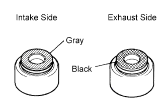
| 7. INSTALL VALVE STEM OIL SEAL |
Apply a light coat of engine oil to a new oil seal.
- NOTICE:
- Pay close attention when installing the intake and exhaust oil seals. For example, installing the intake oil seal into the exhaust side or installing the exhaust oil seal to the intake side can cause installation problems later.
- HINT:
- The intake valve oil seal is gray and the exhaust valve oil seal is black.
 |
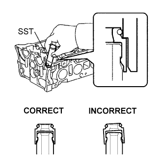
Using SST, push in the oil seal.
- SST
- 09201-41020
- NOTICE:
- Failure to use SST will cause the seal to be damaged or improperly seated.
 |
| 8. INSTALL INTAKE VALVE |
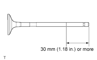
Apply a sufficient coat of engine oil to the tip area of the intake valve shown in the illustration.
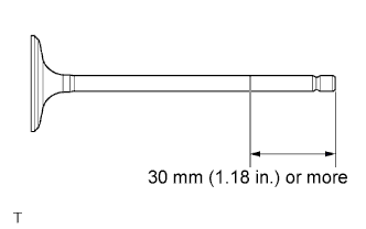 |
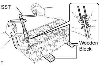
Install the valve, compression spring and spring retainer to the cylinder head.
- NOTICE:
- Install the same parts in the same combination to the original locations.
Using SST and wooden blocks, compress the spring and install the 2 retainer locks.
- SST
- 09202-70020(09202-00010)
 |
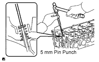
Using a 5 mm pin punch and plastic hammer, lightly tap the valve stem tip to ensure a proper fit.
- NOTICE:
- Be careful not to damage the valve stem tip.
 |
| 9. INSTALL EXHAUST VALVE |
Apply a sufficient coat of engine oil to the tip area of the exhaust valve shown in the illustration.
 |
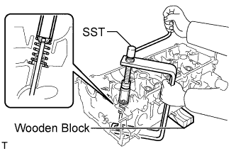
Install the valve, compression spring and spring retainer to the cylinder head.
- NOTICE:
- Install the same parts in the same combination to the original locations.
Using SST and wooden blocks, compress the spring and install the 2 retainer locks.
- SST
- 09202-70020(09202-00010)
 |
Using a 5 mm pin punch and plastic hammer, lightly tap the valve stem tip to ensure a proper fit.
- NOTICE:
- Be careful not to damage the valve stem tip.
 |
| 10. INSTALL VALVE LIFTER |
Assemble the valve lifter and the tip of the valve stem with a light coat of engine oil applied.
- NOTICE:
- Install the valve lifters in their original places.
 |