Cylinder Head -- Removal |
| 1. DISCHARGE FUEL SYSTEM PRESSURE |
- HINT:
| 2. DISCONNECT CABLE FROM NEGATIVE BATTERY TERMINAL |
| 3. REMOVE ENGINE UNDER COVER LH |
| 4. REMOVE ENGINE UNDER COVER RH |
| 5. REMOVE FRONT FENDER APRON SEAL RH |
| 6. REMOVE NO. 1 ENGINE COVER SUB-ASSEMBLY |
Remove the 2 nuts and cover.
 |
| 7. DRAIN ENGINE COOLANT |
- NOTICE:
- Do not remove the radiator cap sub-assembly while the engine and radiator are still hot. Pressurized, hot engine coolant and steam may be released and cause serious burns.
Remove the radiator cap sub-assembly from the radiator assembly.
Loosen the radiator drain cock plug and cylinder block drain cock plug, then drain the coolant.
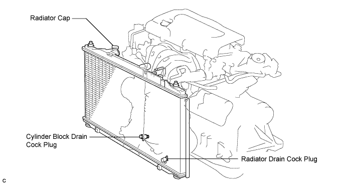
- HINT:
- Collect the coolant in a container and dispose of it according to the regulations in your area.
| 8. DRAIN ENGINE OIL |
Remove the oil filler cap.
Remove the oil drain plug and drain the oil into a container.
| 9. REMOVE WINDSHIELD WIPER LINK ASSEMBLY |
- HINT:
| 10. REMOVE COWL TOP PANEL OUTER SUB-ASSEMBLY |
Remove the 4 bolts, 4 nuts and outer cowl top panel sub-assembly.
 |
| 11. REMOVE AIR CLEANER INLET ASSEMBLY |
Remove the 2 bolts, clamp and air cleaner inlet.
 |
| 12. REMOVE AIR CLEANER CAP SUB-ASSEMBLY |
Disconnect the mass air flow meter connector (*1).
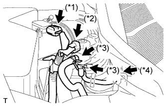 |
Disconnect the purge VSV connector (*2).
Disconnect the 2 purge VSV vacuum hoses (*3).
Disconnect the purge line hose from the clamp (*4).
Disconnect the No. 2 ventilation hose from the air cleaner hose.
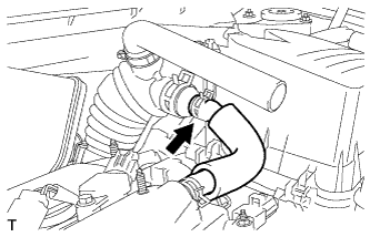 |
Lock the No. 1 air cleaner hose clamp, and then disconnect the No. 1 air cleaner hose from the throttle body.
 |
Remove the 2 bolts and air cleaner cap.
 |
Remove the air cleaner filter element from the air cleaner case.
| 13. REMOVE AIR CLEANER CASE SUB-ASSEMBLY |
Disconnect the hose clamp.
 |
Remove the 3 bolts and air cleaner case.
| 14. REMOVE BATTERY |
Loosen the bolt and nut, and remove the battery clamp.
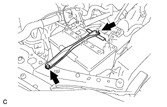 |
Remove the battery and battery tray.
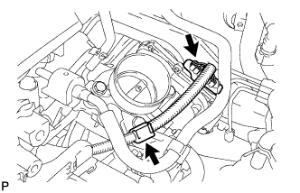
| 15. REMOVE THROTTLE BODY ASSEMBLY |
Disconnect the throttle position sensor connector and wire harness clamp.
 |
Remove the 4 bolts, and then remove the fuel pipe support and throttle body.
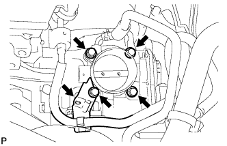 |
Disconnect the purge line hose from the throttle body.
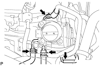 |
Disconnect the water by-pass hose from the throttle body.
Disconnect the No. 2 water by-pass hose from the throttle body.
Disconnect the No. 1 throttle body hose from the throttle body.
Remove the gasket from the intake manifold.
 |
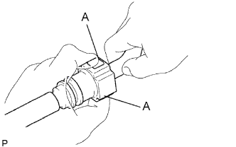
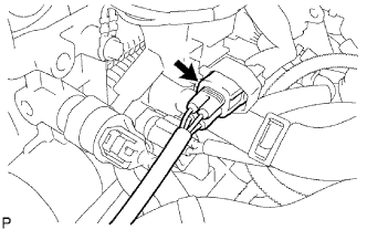
| 16. DISCONNECT FUEL TUBE SUB-ASSEMBLY |
Remove the No. 1 fuel pipe clamp.
 |
Disconnect the connector from the tube while pinching part A with your fingers as shown in the illustration.
- NOTICE:
- Check for contamination in the pipe and around the connector. Clean if necessary and then disconnect the connector.
- Disconnect the connector by hand.
- Do not bend, fold or rotate the nylon tube.
- If the pipe and connector are stuck together, push and pull the connector until it becomes free.
- Put the pipe and connector ends in vinyl bags to prevent damage and contamination.
 |
| 17. REMOVE FUEL DELIVERY PIPE WITH INJECTOR |
Remove the 2 wire harness clamps.
 |
Disconnect the 4 fuel injector connectors.
Remove the 2 bolts, then remove the fuel delivery pipe together with the 4 fuel injectors.
- NOTICE:
- Be careful not to drop the fuel injectors when removing the fuel delivery pipe.
 |
Remove the 2 delivery pipe spacers from the cylinder head.
 |
Remove the 4 insulators from the cylinder head.
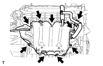
| 18. REMOVE INTAKE MANIFOLD |
Disconnect the union to check valve hose from the brake booster.
Disconnect the camshaft timing oil control valve connector.
 |
Remove the wire harness clamp.
Remove the union to check valve hose from the vacuum hose clamp.
Remove the 5 bolts, 2 nuts and intake manifold.
Remove the gasket from the intake manifold.
 |
| 19. REMOVE NO. 1 INTAKE MANIFOLD INSULATOR |
Remove the intake manifold insulator from the cylinder block.
 |
| 20. REMOVE FRONT EXHAUST PIPE ASSEMBLY |
- HINT:
| 21. REMOVE NO. 2 ENGINE MOUNTING STAY RH |
Remove the 2 bolts and No. 2 mounting stay RH.
 |
| 22. REMOVE ENGINE MOVING CONTROL ROD SUB-ASSEMBLY |
Remove the bolt and disconnect the ground cable.
 |
Remove the 3 bolts and the engine moving control rod with bracket.
 |
| 23. REMOVE NO. 2 ENGINE MOUNTING BRACKET RH |
Remove the 3 bolts and No. 2 mounting bracket RH.
 |
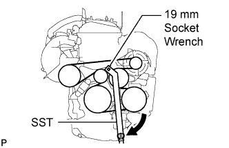
| 24. REMOVE V-RIBBED BELT |
Using SST and 19 mm socket wrench, loosen the V-ribbed belt tensioner arm clockwise, then remove the V-ribbed belt.
- SST
- 09216-42010
- NOTICE:
- Be sure to connect SST and the tools so that they are in line during use.
- When retracting the tensioner, turn it clockwise slowly for 3 seconds or more. Do not apply force rapidly.
- After the tensioner is fully retracted, do not apply force any more than necessary.
 |
| 25. REMOVE GENERATOR ASSEMBLY |
Disconnect the generator connector.
 |
Remove the nut and disconnect the wire harness from terminal B.
Remove the bolt and wire harness clamp bracket.
Remove the wire harness clamps.
Remove the 2 bolts and generator assembly.
 |
| 26. REMOVE OIL LEVEL GAUGE SUB-ASSEMBLY |
| 27. REMOVE OIL LEVEL GAUGE GUIDE |
Remove the bolt and oil level gauge guide.
 |
Remove the O-ring from the oil level gauge guide.
| 28. REMOVE MANIFOLD STAY |
Remove the bolt, nut and stay.
 |
| 29. REMOVE NO. 2 MANIFOLD STAY |
Remove the bolt, nut and stay.
 |
| 30. REMOVE EXHAUST MANIFOLD CONVERTER SUB-ASSEMBLY |
Remove the 4 bolts and No. 1 insulator.
 |
Disconnect the air-fuel ratio sensor connector.
 |
Remove the 5 nuts, manifold converter and gasket.
 |
| 31. REMOVE CHAIN SUB-ASSEMBLY |
- HINT:
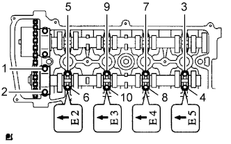
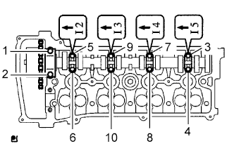
| 32. REMOVE NO. 2 CAMSHAFT |
Using several steps, uniformly loosen and remove the 10 bearing cap bolts in the sequence shown in the illustration.
 |
Remove the 5 bearing caps and No. 2 camshaft.
| 33. REMOVE CAMSHAFT |
Using several steps, uniformly loosen and remove the 10 bearing cap bolts in the sequence shown in the illustration.
 |
Remove the 5 bearing caps and camshaft.
| 34. REMOVE CAMSHAFT TIMING OIL CONTROL VALVE ASSEMBLY |
Disconnect the camshaft timing oil control valve assembly connector.
 |
Remove the bolt and camshaft timing oil control valve assembly.
| 35. DISCONNECT RADIATOR HOSE INLET |
Remove the clamp and disconnect the radiator hose inlet.
 |
| 36. DISCONNECT ENGINE WIRE |
Disconnect the radio setting condenser connector.
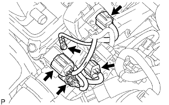 |
Disconnect the engine oil pressure switch connector.
Disconnect the engine coolant temperature sensor connector.
Disconnect the camshaft position sensor connector.
Remove the bolt and ground cable.
| 37. REMOVE NO. 2 CAMSHAFT BEARING |
Remove the No. 2 camshaft bearing.
 |
| 38. REMOVE CYLINDER HEAD SUB-ASSEMBLY |
Using several steps, uniformly loosen and remove the 10 cylinder head bolts and 10 plate washers with a 10 mm bi-hexagon wrench in the sequence shown in the illustration.
- NOTICE:
- Head warpage or cracking could result from removing the bolts in the wrong order.
 |
Using a screwdriver with its tip wrapped with tape, pry between the cylinder head and cylinder block, and remove the cylinder head.
- NOTICE:
- Be careful not to damage the contact surfaces of the cylinder head and cylinder block.
 |
| 39. REMOVE CYLINDER HEAD GASKET |
Remove the cylinder head gasket.
 |