Camshaft -- Inspection |
| 1. INSPECT CAMSHAFT TIMING GEAR ASSEMBLY |
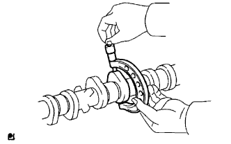
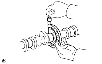
Check the lock of the camshaft timing gear.
Clamp the camshaft in a vise, and confirm that the camshaft timing gear is locked.
- NOTICE:
- Be careful not to damage the camshaft.
 |
Release the lock pin.
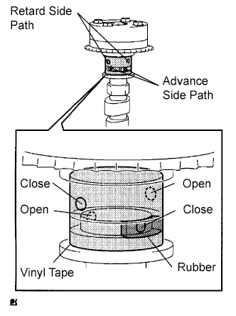
Cover the 4 oil paths of the cam journal with vinyl tape as shown in the illustration.
- HINT:
- The 2 advance side paths are provided in the groove of the camshaft. Plug one of the paths with a rubber piece.
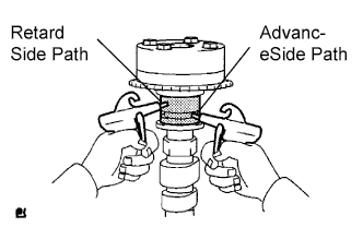
Break through the tape of the advance side path and the retard side path on the opposite side to the hole of the advance side path, as shown in the illustration.
Apply approximately 200 kPa (2.0 kgf/cm2, 28 psi) of air pressure to the two broken paths.
- CAUTION:
- Cover the paths with a piece of cloth when applying pressure to keep oil from splashing.
Check that the camshaft timing gear revolves in the advance direction when reducing the air pressure of the retard side path.
- OK:
- Gear rotates in the advance direction.
- HINT:
- This operation releases the lock pin for the most retarded position.
When the camshaft timing gear reaches the most advanced position, remove the air gun from the retard side path and advance side path, in that order.
- NOTICE:
- Do not remove the air gun from the advance side path first. The gear may abruptly shift in the retard direction and break the lock pin.
Check for smooth rotation.
Rotate the camshaft timing gear within its movable range several times, but do not turn it to the most retarded position. Check that the gear rotates smoothly.
- OK:
- Gear rotates smoothly.
- NOTICE:
- Do not use an air gun to check for smooth operation.
Check the lock in the most retarded position.
Confirm that the camshaft timing gear is locked at the most retarded position.
| 2. INSPECT CAMSHAFT |
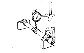
Inspect the camshaft for runout.
Place the camshaft on V-blocks.
Using a dial indicator, measure the circle runout at the center journal.
- Maximum circle runout:
- 0.03 mm (0.0012 in.)
 |
Inspect the cam lobes.
Using a micrometer, measure the cam lobe height.
- Standard cam lobe height:
- 47.306 to 47.406 mm (1.8624 to 1.8664 in.)
- Minimum cam lobe height:
- 47.196 mm (1.8581 in.)
 |
Inspect the camshaft journals.
Using a micrometer, measure the journal diameter.
- Standard journal diameter:
Journal Position Specified Condition No. 1 35.971 to 35.985 mm (1.4162 to 1.4167 in.) Other 22.959 to 22.975 mm (0.9039 to 0.9045 in.)
 |
| 3. INSPECT NO. 2 CAMSHAFT |
Inspect the camshaft for runout.
Place the camshaft on V-blocks.
Using a dial indicator, measure the circle runout at the center journal.
- Maximum circle runout:
- 0.03 mm (0.0012 in.)
|
Inspect the cam lobes.
Using a micrometer, measure the cam lobe height.
- Standard cam lobe height:
- 45.983 to 46.083 mm (1.8104 to 1.8143 in.)
- Minimum cam lobe height:
- 45.873 mm (1.8060 in.)
|
Inspect the camshaft journals.
Using a micrometer, measure the journal diameter.
- Standard journal diameter:
Journal Position Specified Condition No. 1 35.971 to 35.985 mm (1.4162 to 1.4167 in.) Other 22.959 to 22.975 mm (0.9039 to 0.9045 in.)
|