Dtc P0500 Vehicle Speed Sensor A
DESCRIPTION
WIRING DIAGRAM
INSPECTION PROCEDURE
READ VALUE USING INTELLIGENT TESTER (VEHICLE SPEED)
CHECK COMBINATION METER SYSTEM
CHECK HARNESS AND CONNECTOR (COMBINATION METER - ECM)
CHECK HARNESS AND CONNECTOR (ECM - NO. 3 JUNCTION BLOCK)
DTC P0500 Vehicle Speed Sensor "A" |
DESCRIPTION
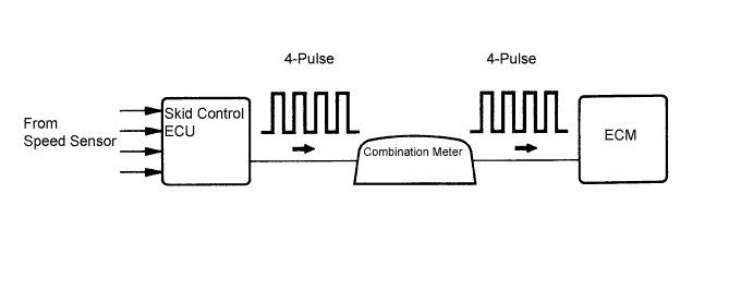
The speed sensor detects the wheel speed and sends the appropriate signals to the skid control ECU. The skid control ECU converts these wheel speed signals into a 4-pulse signal and outputs it to the ECM via the combination meter. The ECM determines the vehicle speed based on the frequency of these pulse signals.DTC No.
| DTC Detection Condition
| Trouble Area
|
P0500
| Vehicle speed signal from vehicle speed sensor is cut for 0.14 sec. or more while cruise control is in operation
| - Vehicle speed sensor
- Vehicle speed sensor signal circuit
- Combination meter
- ECM
|
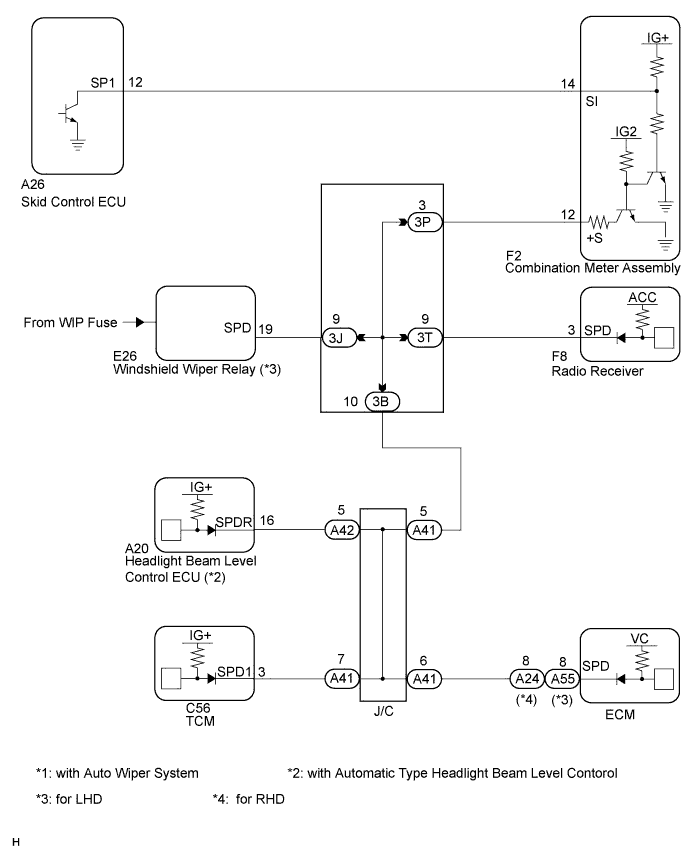
WIRING DIAGRAM
INSPECTION PROCEDURE
- HINT:
- Read freeze frame data using the intelligent tester or the OBD II scan tool. The ECM records vehicle and driving condition information as freeze frame data the moment a DTC is stored. When troubleshooting, freeze frame data can be helpful in determining whether the vehicle was running or stopped, whether the engine was warmed up or not, whether the air-fuel ratio was lean or rich, as well as other data recorded at the time of a malfunction (CAMRY_ACV40 RM000000PDS01FX.html).
| 1.READ VALUE USING INTELLIGENT TESTER (VEHICLE SPEED) |
Connect the intelligent tester to the DLC3.
Turn the ignition switch to the ON position.
Turn the tester on.
Select the following menu items: Powertrain / Engine / Date List / Vehicle Speed.
Drive the vehicle.
Read the value displayed on the tester.
- OK:
- Vehicle speeds displayed on tester and speedometer display are equal.
| OK |
|
|
|
| CHECK INTERMITTENT PROBLEMS |
|
| 2.CHECK COMBINATION METER SYSTEM |
The circuits that send vehicle speed signals to this system are inspected in the meter system (CAMRY_ACV40 RM000002UD701TX.html).
During inspection for the meter section, if there is an instruction that indicates to go back inspections for each system, proceed to the next step.
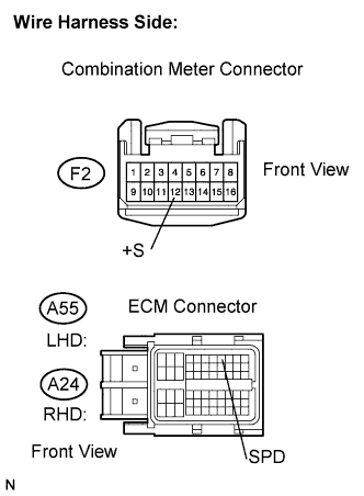
| 3.CHECK HARNESS AND CONNECTOR (COMBINATION METER - ECM) |
Disconnect the A24 or A55 ECM connector.
Disconnect the F2 combination meter connector.
Measure the resistance according to the value(s) in the table below.
Measure the resistance.
- Standard resistance (Check for open):
- RHD:
Tester Connection
| Specified Condition
|
+S (F2-12) - SPD (A24-8)
| Below 1 Ω
|
- LHD:
Tester Connection
| Specified Condition
|
+S (F2-12) - SPD (A55-8)
| Below 1 Ω
|
- Standard resistance (Check for short):
- RHD:
Tester Connection
| Specified Condition
|
+S (F2-12) or SPD (A24-8) - Body ground
| 10 kΩ or higher
|
- LHD:
Tester Connection
| Specified Condition
|
+S (F2-12) or SPD (A55-8) - Body ground
| 10 kΩ or higher
|
Reconnect the ECM connector.
Reconnect the combination meter connector.
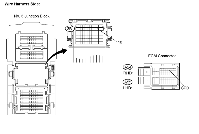
| 4.CHECK HARNESS AND CONNECTOR (ECM - NO. 3 JUNCTION BLOCK) |
Disconnect the A24 or A55 ECM connector.
Disconnect the 3B No. 3 junction block connector.
Measure the resistance according to the value(s) in the table below.
- Standard resistance (Check for open):
- RHD:
Tester Connection
| Specified Condition
|
3B-10 - SPD (A24-8)
| Below 1 Ω
|
- LHD:
Tester Connection
| Specified Condition
|
3B-10 - SPD (A55-8)
| Below 1 Ω
|
Reconnect the ECM connector.
Reconnect the No. 3 junction block connector.
| | REPAIR OR REPLACE HARNESS OR CONNECTOR (ECM - NO. 3 JUNCTION BLOCK) |
|
|
| OK |
|
|
|
| REPAIR OR REPLACE HARNESS OR CONNECTOR (NO. 3 JUNCTION BLOCK) |
|