Dtc P0443 Evaporative Emission Control System Purge Control Valve Circuit
DESCRIPTION
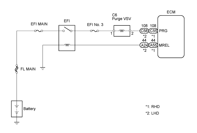
WIRING DIAGRAM
INSPECTION PROCEDURE
PERFORM ACTIVE TEST USING INTELLIGENT TESTER
INSPECT PURGE VSV (OPERATION)
INSPECT PURGE VSV (POWER SOURCE VOLTAGE)
CHECK HARNESS AND CONNECTOR (ECM - PURGE VSV)
CHECK HARNESS AND CONNECTOR (EFI NO. 3 FUSE - ENGINE ROOM J/B (EFI RELAY))
DTC P0443 Evaporative Emission Control System Purge Control Valve Circuit |
DESCRIPTION
To reduce HC emissions, evaporated fuel from the fuel tank is routed through the charcoal canister to the intake manifold for combustion in the cylinders.The ECM changes the duty signal to the VSV for EVAP so that the intake quantity of HC emissions is appropriate for the driving conditions (engine load, engine speed, vehicle speed, etc.) after the engine is warmed up.DTC No.
| DTC Detection Condition
| Trouble Area
|
P0443
| Proper response to ECM command does not occur
(1 trip detection logic)
| - Open or short in purge VSV circuit
- Purge VSV
- ECM
|
WIRING DIAGRAM
INSPECTION PROCEDURE
| 1.PERFORM ACTIVE TEST USING INTELLIGENT TESTER |
Disconnect the vacuum hose from the VSV for EVAP.
Connect the intelligent tester to the DLC3.
Start the engine and turn the tester on.
Enter the following menus: Powertrain / Engine / Active Test / Activate the VSV for EVAP Control. Press the right or left button.
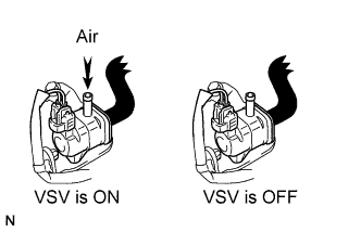
Check if air is sucked into the port when operating the VSV for EVAP using the intelligent tester.
- Standard:
Tester Operation
| Specified Condition
|
VSV is OFF
| No air sucked
|
Reconnect the vacuum hose.
| | CHECK FOR INTERMITTENT PROBLEMS |
|
|
| 2.INSPECT PURGE VSV (OPERATION) |
Disconnect the C6 purge VSV connector.
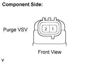
Measure the resistance between the terminals of the purge VSV.
- Standard resistance:
- 23 to 26 Ω at 20°C (68°F)
Reconnect the purge VSV connector.
| | REPLACE VACUUM SWITCHING VALVE |
|
|
| 3.INSPECT PURGE VSV (POWER SOURCE VOLTAGE) |
Disconnect the C6 purge VSV connector.
Turn the ignition switch to the ON position.
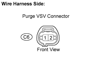
Measure the voltage between the terminal of the wire harness side connector and body ground.
- Standard voltage:
Tester Connection
| Specified Condition
|
Purge VSV (C6-2) - Body ground
| 9 to 14 V
|
Reconnect the purge VSV connector.
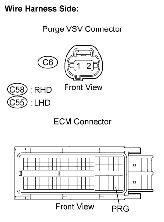
| 4.CHECK HARNESS AND CONNECTOR (ECM - PURGE VSV) |
Disconnect the C6 purge VSV connector.
Disconnect the C58 (RHD) or C55 (LHD) ECM connector.
Measure the resistance between the terminals.
- Standard resistance (Check for open):
- RHD:
Tester Connection
| Specified Condition
|
Purge VSV (C6-2) - PRG (C58-108)
| Below 1 Ω
|
- LHD:
Tester Connection
| Specified Condition
|
Purge VSV (C6-2) - PRG (C55-108)
| Below 1 Ω
|
- Standard resistance (Check for short):
- RHD:
Tester Connection
| Specified Condition
|
Purge VSV (C6-2) or PRG (C58-108) - Body ground
| 10 kΩ or higher
|
- LHD:
Tester Connection
| Specified Condition
|
Purge VSV (C6-2) or PRG (C55-108) - Body ground
| 10 kΩ or higher
|
Reconnect the ECM connector.
Reconnect the purge VSV connector.
| | REPAIR OR REPLACE HARNESS OR CONNECTOR |
|
|
| OK |
|
|
|
| REPAIR OR REPLACE POWER SOURCE CIRCUIT |
|
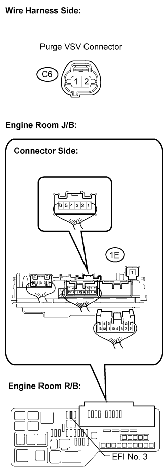
| 5.CHECK HARNESS AND CONNECTOR (EFI NO. 3 FUSE - ENGINE ROOM J/B (EFI RELAY)) |
Inspect the EFI No. 3 fuse.
Remove the EFI No. 3 fuse from the engine room J/B.
Measure the EFI No. 3 fuse resistance.
- Standard resistance:
- Below 1 Ω
Remove the engine room J/B from the engine room R/B.
Disconnect the C6 purge VSV connector.
Measure the resistance between the terminals.
- Standard resistance:
- Check for open:
Tester Connection
| Specified Condition
|
Purge VSV (C6-1) - Engine room R/B (1E-6)
| Below 1 Ω
|
Reinstall the engine room J/B.
Reconnect the purge VSV connector.
| | REPAIR OR REPLACE HARNESS OR CONNECTOR |
|
|