CHECK ANY OTHER DTCS OUTPUT (IN ADDITION TO DTC P2A00)
INSPECT AIR-FUEL RATIO SENSOR (HEATER RESISTANCE)
CHECK HARNESS AND CONNECTOR (A/F SENSOR - ECM)
PERFORM CONFIRMATION DRIVING PATTERN
CHECK WHETHER DTC OUTPUT RECURS (DTC P2A00)
PERFORM CONFIRMATION DRIVING PATTERN
CHECK WHETHER DTC OUTPUT RECURS (DTC P2A00)
DTC P2A00 A/F Sensor Circuit Slow Response (Bank 1 Sensor 1) |
- HINT:
- Sensor 1 refers to the sensor mounted in front of the Three-Way Catalytic Converter (TWC) and located near the engine assembly.
DESCRIPTION
Refer to DTC P2195 (Link).| DTC No. | DTC Detection Condition | Trouble Area |
| P2A00 | Calculated value of air-fuel ratio (A/F) sensor response rate deterioration level less than threshold (2 trip detection logic) |
|
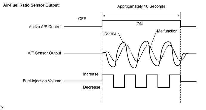
MONITOR DESCRIPTION
After the engine is warmed up, the ECM performs air-fuel ratio feedback control to maintain the air-fuel ratio at the stoichiometric level. In addition, active A/F control is performed for approximately 10 seconds after the preconditions are met in order to measure the A/F sensor response rate. During active A/F control, the ECM forcibly increases and decreases the injection volume by a certain amount, based on the stoichiometric air-fuel ratio learned during normal air-fuel ratio control, and measures the A/F sensor response rate. The ECM receives a signal from the A/F sensor while performing active A/F control and uses it to calculate the A/F sensor response rate deterioration level.If the A/F sensor response rate deterioration level is less than the threshold, the ECM interprets this as a malfunction and sets the DTC.
CONFIRMATION DRIVING PATTERN
- HINT:
- Performing this confirmation pattern will activate the A/F sensor response monitor.

Connect the intelligent tester to the DLC3.
- Turn the ignition switch to the ON position.
- Turn the tester on.
- Clear the DTCs (if set) (CAMRY_ACV40 RM000000PDK081X.html).
- Select the following menu items: Powertrain / Engine and ECT / Data List / Monitor Status.
- Check that "O2S (A/FS) Monitor" is "Incmpl".
- Start the engine and warm it up. (Proceed to "A")
- Drive the vehicle at a constant speed of between 64 km/h and 120 km/h (40 mph and 75 mph) for 3 minutes. (Proceed to "B")
- Check that the status of the "O2S (A/FS) Monitor" is "Compl".
- Select the following menu items: Powertrain / Engine and ECT / DTC.
- Check if any DTCs (any pending DTCs) are set.
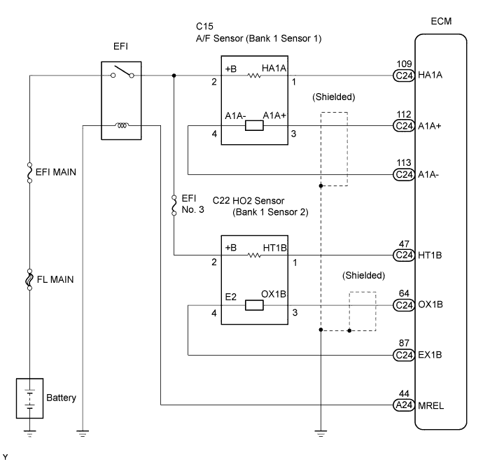
WIRING DIAGRAM
INSPECTION PROCEDURE
- HINT:
- Intelligent tester only:
- Malfunctioning areas can be identified by performing the "Control the Injection Volume for A/F Sensor" function provided in the Active Test. The "Control the Injection Volume for A/F Sensor" function can help determine whether the Air-Fuel Ratio (A/F) sensor, Heated Oxygen (HO2) sensor and other potential trouble areas are malfunctioning.
- The following instructions describe how to conduct the "Control the Injection Volume for A/F Sensor" operation using the intelligent tester.
- Connect the intelligent tester to the DLC3.
- Start the engine and turn the tester on.
- Warm up the engine at an engine speed of 2,500 rpm for approximately 90 seconds.
- On the tester, select the following menu items: Powertrain / Engine and ECT / Active Test / Control the Injection Volume for A/F Sensor.
- Perform the "Control the Injection Volume for A/F Sensor" operation with the engine idling (press the RIGHT or LEFT button to change the fuel injection volume).
- Monitor the voltage outputs of the A/F and HO2 sensors (AFS B1 S1 and O2S B1 S2) displayed on the tester.
- HINT:
- The "Control the Injection Volume for A/F Sensor" operation lowers the fuel injection volume by 12.5% or increases the injection volume by 25%.
- The sensors react in accordance with increases and decreases in the fuel injection volume.
- Standard:
Tester Display
(Sensor)Injection Volume Status Voltage AFS B1 S1
(A/F)+25% Rich Less than 3.0 -12.5% Lean More than 3.35 O2S B1 S2
(HO2)+25% Rich More than 0.5 -12.5% Lean Less than 0.4
- NOTICE:
- The A/F sensor has an output delay of a few seconds and the HO2 sensor has a maximum output delay of approximately 20 seconds.
| Case | A/F Sensor (Sensor 1) Output Voltage | HO2 Sensor (Sensor 2) Output Voltage | Main Suspected Trouble Area | ||
| 1 | Injection Volume +25% -12.5% |  | Injection Volume +25% -12.5% | | - |
| Output Voltage More than 3.35 V Less than 3.0 V |  | Output Voltage More than 0.5 V Less than 0.4 V |  | ||
| 2 | Injection Volume +25% -12.5% | | Injection Volume +25% -12.5% | |
|
| Output Voltage Almost no reaction |  | Output Voltage More than 0.5 V Less than 0.4 V | | ||
| 3 | Injection Volume +25% -12.5% | | Injection Volume +25% -12.5% | |
|
| Output Voltage More than 3.35 V Less than 3.0 V | | Output Voltage Almost no reaction | | ||
| 4 | Injection volume +25% -12.5% | | Injection Volume +25% -12.5% | |
|
| Output Voltage Almost no reaction | | Output voltage Almost no reaction | | ||
- Following the "Control the Injection Volume for A/F Sensor" procedure enables technicians to check and graph the voltage outputs of both the A/F and HO2 sensors.
- To display the graph, select the following menu items on the tester: Powertrain / Engine and ECT / Active Test / Control the Injection Volume for A/F Sensor / Enter / View / AFS B1 S1 and O2S B1 S2.
- HINT:
- DTC P2A00 may be set when the air-fuel ratio is stuck rich or lean.
- A low A/F sensor voltage could be caused by a rich air-fuel mixture. Check for conditions that would cause the engine to run rich.
- A high A/F sensor voltage could be caused by a lean air-fuel mixture. Check for conditions that would cause the engine to run lean.
- Read freeze frame data using the intelligent tester. The ECM records vehicle and driving condition information as freeze frame data the moment a DTC is stored. When troubleshooting, freeze frame data can help determine if the vehicle was moving or stationary, if the engine was warmed up or not, if the air-fuel ratio was lean or rich, and other data from the time the malfunction occurred.
| 1.CHECK ANY OTHER DTCS OUTPUT (IN ADDITION TO DTC P2A00) |
Connect the intelligent tester to the DLC3.
Turn the ignition switch to the ON position.
Turn the tester on.
Select the following menu items: Powertrain / Engine and ECT / DTC.
Read the DTCs.
- Result:
Display (DTC Output) Proceed to P2A00 A P2A00 and other DTCs B
|
| ||||
| A | |
| 2.INSPECT AIR-FUEL RATIO SENSOR (HEATER RESISTANCE) |
Disconnect the C15 A/F sensor connector.
 |
Measure the resistance between the terminals of the A/F sensor connector.
- Standard resistance:
Tester Connection Specified Condition HA1A (1) - +B (2) 1.8 to 3.4 Ω at 20°C (68°F) HA1A (1) - A1A- (4) 10 kΩ or higher
Reconnect the A/F sensor connector.
|
| ||||
| OK | |
| 3.CHECK HARNESS AND CONNECTOR (A/F SENSOR - ECM) |
Disconnect the C15 A/F sensor connector.
 |
Disconnect the C24 ECM connector.
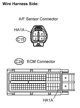
Measure the resistance between the terminals of the wire harness side connectors.
- Standard resistance (Check for open):
Tester Connection Specified Condition HA1A (C15-1) - HA1A (C24-109) Below 1 Ω
- Standard resistance (Check for short):
Tester Connection Specified Condition HA1A (C15-1) or HA1A (C24-109) - Body ground 10 kΩ or higher
Reconnect the A/F sensor connector.
Reconnect the ECM connector.
|
| ||||
| OK | |
| 4.PERFORM CONFIRMATION DRIVING PATTERN |
| NEXT | |
| 5.CHECK WHETHER DTC OUTPUT RECURS (DTC P2A00) |
Connect the intelligent tester to the DLC3.
Turn the ignition switch to the ON position and turn the tester on.
Select the following menu items: Powertrain / Engine and ECT / DTC.
Read pending DTCs.
- Result:
Display (DTC Output) Proceed to P2A00 A No output B
|
| ||||
| A | |
| 6.REPLACE AIR-FUEL RATIO SENSOR |
| NEXT | |
| 7.PERFORM CONFIRMATION DRIVING PATTERN |
| NEXT | |
| 8.CHECK WHETHER DTC OUTPUT RECURS (DTC P2A00) |
Connect the intelligent tester to the DLC3.
Turn the ignition switch to the ON position and turn the tester on.
Select the following menu items: Powertrain / Engine and ECT / DTC.
Read pending DTCs.
- Result:
Display (DTC Output) Proceed to No output A P2A00 B
|
| ||||
| A | ||
| ||