Can Communication System Ecm Communication Stop Mode
DESCRIPTION
WIRING DIAGRAM
INSPECTION PROCEDURE
CHECK HARNESS AND CONNECTOR (ECM - BATTERY AND BODY GROUND)
CAN COMMUNICATION SYSTEM - ECM Communication Stop Mode |
DESCRIPTION
Detection Item
| Symptom
| Trouble Area
|
ECM Communication Stop Mode
| Either condition is met:
- "Engine" is not displayed on "Bus Check".
- "ECM Communication Stop Mode" in "DTC Combination Table" applies.
| - Power source or inside ECM
- Harness or connector
- ECM
|
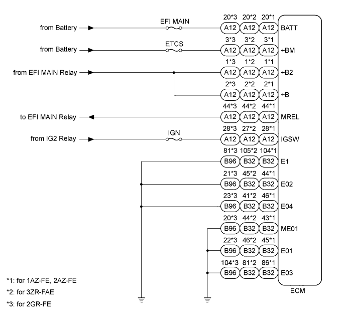
WIRING DIAGRAM
INSPECTION PROCEDURE
| 1.CHECK HARNESS AND CONNECTOR (ECM - BATTERY AND BODY GROUND) |
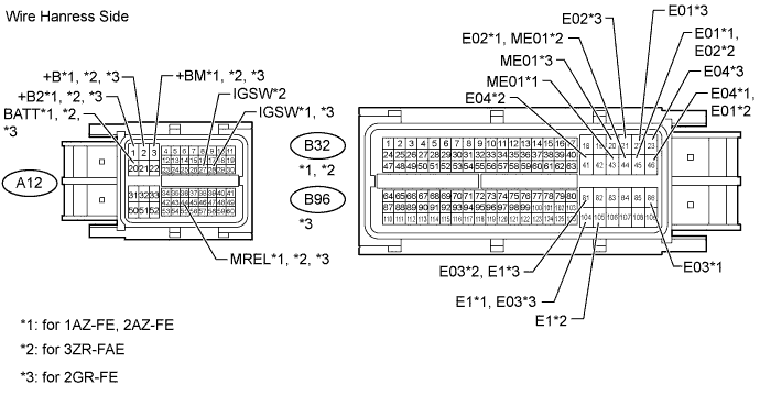
Disconnect the A12, B32*1, *2 and B96*3 ECM connectors.
- *1: for 1AZ-FE, 2AZ-FE
- *2: for 3ZR-FAE
- *3: for 2GR-FE
Measure the resistance according to the value(s) in the table below.
- Standard Resistance:
- for 1AZ-FE, 2AZ-FE:
Tester Connection
| Condition
| Specified Condition
|
B32-104 (E1) - Body ground
| Always
| Below 1 Ω
|
B32-45 (E01) - Body ground
| Always
| Below 1 Ω
|
B32-44 (E02) - Body ground
| Always
| Below 1 Ω
|
B32-86 (E03) - Body ground
| Always
| Below 1 Ω
|
B32-46 (E04) - Body ground
| Always
| Below 1 Ω
|
B32-43 (ME01) - Body ground
| Always
| Below 1 Ω
|
- for 3ZR-FAE:
Tester Connection
| Condition
| Specified Condition
|
B32-105 (E1) - Body ground
| Always
| Below 1 Ω
|
B32-46 (E01) - Body ground
| Always
| Below 1 Ω
|
B32-45 (E02) - Body ground
| Always
| Below 1 Ω
|
B32-81 (E03) - Body ground
| Always
| Below 1 Ω
|
B32-41 (E04) - Body ground
| Always
| Below 1 Ω
|
B32-44 (ME01) - Body ground
| Always
| Below 1 Ω
|
- for 2GR-FE:
Tester Connection
| Condition
| Specified Condition
|
B96-81 (E1) - Body ground
| Always
| Below 1 Ω
|
B96-22 (E01) - Body ground
| Always
| Below 1 Ω
|
B96-21 (E02) - Body ground
| Always
| Below 1 Ω
|
B96-104 (E03) - Body ground
| Always
| Below 1 Ω
|
B96-23 (E04) - Body ground
| Always
| Below 1 Ω
|
B96-20 (ME01) - Body ground
| Always
| Below 1 Ω
|
Measure the voltage according to the value(s) in the table below.
- Standard Voltage:
- for 1AZ-FE, 2AZ-FE, 2GR-FE:
Tester Connection
| Switch Condition
| Specified Condition
|
A12-1 (+B2) - Body ground
| Battery's positive (+) voltage applied to terminal MREL
| 11 to 14 V
|
A12-2 (+B) - Body ground
| Battery's positive (+) voltage applied to terminal MREL
| 11 to 14 V
|
A12-3 (+BM) - Body ground
| Always
| 11 to 14 V
|
A12-20 (BATT) - Body ground
| Always
| 11 to 14 V
|
A12-28 (IGSW) - Body ground
| Ignition switch on (IG)
| 11 to 14 V
|
- for 3ZR-FAE:
Tester Connection
| Switch Condition
| Specified Condition
|
A12-1 (+B2) - Body ground
| Battery's positive (+) voltage applied to terminal MREL
| 11 to 14 V
|
A12-2 (+B) - Body ground
| Battery's positive (+) voltage applied to terminal MREL
| 11 to 14 V
|
A12-3 (+BM) - Body ground
| Always
| 11 to 14 V
|
A12-20 (BATT) - Body ground
| Always
| 11 to 14 V
|
A12-27 (IGSW) - Body ground
| Ignition switch on (IG)
| 11 to 14 V
|
| | REPAIR OR REPLACE HARNESS OR CONNECTOR |
|
|