Dtc B1207 Certification Ecu Communication Malfunction
DESCRIPTION
WIRING DIAGRAM
INSPECTION PROCEDURE
CHECK FOR DTC
DISCONNECT CABLE FROM NEGATIVE BATTERY TERMINAL
CHECK CAN BUS LINE FOR DISCONNECTION (CERTIFICATION ECU BRANCH WIRE)
CHECK HARNESS AND CONNECTOR (CERTIFICATION ECU - BATTERY AND BODY GROUND)
DTC B1207 Certification ECU Communication Malfunction |
DESCRIPTION
DTC Code
| DTC Detection Condition
| Trouble Area
|
B1207
| There is no communication from the certification ECU.
| - Power source circuit of certification ECU
- Certification ECU branch wire or connector
- Certification ECU
|
- HINT:
- For vehicles with an entry and start system only.
WIRING DIAGRAM
INSPECTION PROCEDURE
- NOTICE:
- Turn the ignition switch off before measuring the resistance of the main wire and the branch wire.
- After the ignition switch is turned off, check that the key reminder warning system and light reminder buzzer are not in operation.
- Before measuring the resistance, leave the vehicle for at least 1 minute and do not operate the ignition switch, any switches or doors. If doors need to be opened in order to check connectors, open the doors and leave them open.
- HINT:
- Operating the ignition switch, any switches or any doors triggers related ECU and sensor communication with the CAN, which causes resistance variation.
Connect the intelligent tester to the DLC3.
Turn the ignition switch on (IG).
Clear the DTC.
Check for DTC.
ResultResult
| Proceed to
|
DTC is not output.
| A
|
DTC is output.
| B
|
| | Go to ENTRY AND START SYSTEM |
|
|
| 2.DISCONNECT CABLE FROM NEGATIVE BATTERY TERMINAL |
Disconnect the cable from the negative (-) battery terminal before measuring the resistance of the main wire and the branch wire.
- CAUTION:
- Wait at least 90 seconds after disconnecting the cable from the negative (-) battery terminal to disable the SRS system.
- NOTICE:
- w/ Navigation System (for HDD):
After the ignition switch is turned off, the HDD navigation system requires approximately a minute to record various types of memory and settings. As a result, after turning the ignition switch off, wait a minute or more before disconnecting the cable from the negative (-) battery terminal.
- When disconnecting the cable, some systems need to be initialized after the cable is reconnected.
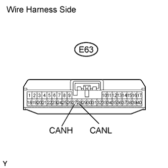
| 3.CHECK CAN BUS LINE FOR DISCONNECTION (CERTIFICATION ECU BRANCH WIRE) |
Disconnect the E63 certification ECU connector.
Measure the resistance according to the value(s) in the table below.
- Standard Resistance:
Tester Connection
| Switch Condition
| Specified Condition
|
E63-27 (CANH) - E63-28 (CANL)
| Ignition switch off
| 54 to 69 Ω
|
| | REPAIR OR REPLACE CAN BRANCH WIRE CONNECTED TO CERTIFICATION ECU (CANH, CANL) |
|
|
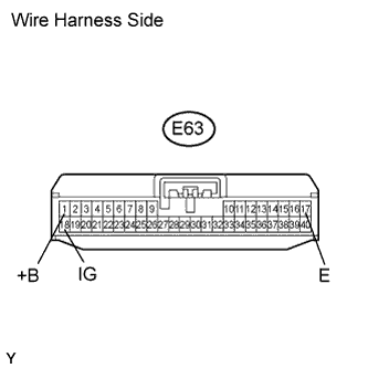
| 4.CHECK HARNESS AND CONNECTOR (CERTIFICATION ECU - BATTERY AND BODY GROUND) |
Connect the cable to the negative (-) battery terminal.
- NOTICE:
- When disconnecting the cable, some systems need to be initialized after the cable is reconnected.
Measure the resistance according to the value(s) in the table below.
- Standard Resistance:
Tester Connection
| Condition
| Specified Condition
|
E63-17 (E) - Body ground
| Always
| Below 1 Ω
|
Measure the voltage according to the value(s) in the table below.
- Standard Voltage:
Tester Connection
| Condition
| Specified Condition
|
E63-1 (+B) - Body ground
| Always
| 11 to 14 V
|
E63-18 (IG) - Body ground
| Ignition switch on (IG)
| 11 to 14 V
|
| | REPAIR OR REPLACE HARNESS OR CONNECTOR |
|
|
| OK |
|
|
|
| REPLACE CERTIFICATION ECU |
|