Meter / Gauge System Diagnosis System
Meter. Toyota Rav4. Aca30, 33, 38 Gsa33 Zsa30, 35
DESCRIPTION
CHECK DLC3
Meter / Gauge System -- Diagnosis System |
Data of the system can be read through the Data Link Connector 3 (DLC3) of the vehicle. Therefore, when the system seems to be malfunctioning, use the intelligent tester to check for a malfunction and repair it.
|
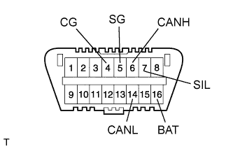
The vehicle uses the ISO 15765-4 for communication protocol. The terminal arrangement of the DLC3 complies with ISO 15031-03 and matches the ISO 15765-4 format.
Symbols (Terminal No.)
| Terminal Description
| Condition
| Specified Condition
|
SIL (7) - SG (5)
| Bus "+" line
| During transmission
| Pulse generation
|
CG (4) - Body ground
| Chassis ground
| Always
| Below 1 Ω
|
SG (5) - Body ground
| Signal ground
| Always
| Below 1 Ω
|
BAT (16) - Body ground
| Battery positive
| Always
| 11 to 14 V
|
CANH (6) - CANL (14)
| HIGH-level CAN bus line
| Ignition switch off*
| 54 to 69 Ω
|
CANH (6) - Battery positive
| HIGH-level CAN bus line
| Ignition switch off*
| 1 MΩ or higher
|
CANH (6) - CG (4)
| HIGH-level CAN bus line
| Ignition switch off*
| 200 Ω or higher
|
CANL (14) - Battery positive
| LOW-level CAN bus line
| Ignition switch off*
| 1 MΩ or higher
|
CANL (14) - CG (4)
| LOW-level CAN bus line
| Ignition switch off*
| 200 Ω or higher
|
- NOTICE:
- *: Before measuring the resistance, leave the vehicle as is for at least 1 minute and do not operate the ignition switch, other switches or doors.
- If the result is not as specified, the DLC3 may have a malfunction. Repair or replace the harness and connector.
- HINT:
- Connect the cable of the intelligent tester to the DLC3, turn the ignition switch on (IG) and attempt to use the tester. If the display indicates that a communication error has occurred, there is a problem either with the vehicle or with the tester.
- If communication is normal when the tester is connected to another vehicle, inspect the DLC3 of the original vehicle.
- If communication is still not possible when the tester is connected to another vehicle, the problem may be in the tester itself. Consult the Service Department listed in the tester's instruction manual.
