Cruise Control System Clutch Switch Circuit
DESCRIPTION
WIRING DIAGRAM
INSPECTION PROCEDURE
INSPECT CLUTCH SWITCH ASSEMBLY
CHECK ECM
CRUISE CONTROL SYSTEM - Clutch Switch Circuit |
DESCRIPTION
This circuit sends signals to the ECM depending on the clutch switch condition.
WIRING DIAGRAM
INSPECTION PROCEDURE
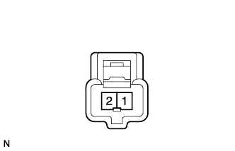
| 1.INSPECT CLUTCH SWITCH ASSEMBLY |
Remove the clutch switch.
Measure the resistance of the switch.
- Standard resistance:
Tester Connection
| Specified Condition
|
1 - 2
| Below 1 Ω
|
| | REPLACE CLUTCH SWITCH ASSEMBLY |
|
|
Disconnect the B32*1 or A12*2 ECM connection.
- *1: for 1AZ-FE, 2AZ-FE
- *2: for 3ZR-FAE
Turn the ignition switch on (IG).
Measure the voltage of the wire harness side connector.
- Standard voltage:
for 1AZ-FE, 2AZ-FETester Connection
| Switch Condition
| Specified Condition
|
B32-56 (D) - Body ground
| Clutch switch ON
| 11 to 14 V
|
for 3ZR-FAETester Connection
| Switch Condition
| Specified Condition
|
A12-47 (D) - Body ground
| Clutch switch ON
| 11 to 14 V
|
| | REPAIR OR REPLACE HARNESS AND CONNECTOR |
|
|
| OK |
|
|
|
| PROCEED TO NEXT CIRCUIT INSPECTION SHOWN IN PROBLEM SYMPTOMS TABLE |
|