Dtc B1422/22 Compressor Lock Sensor Circuit
DESCRIPTION
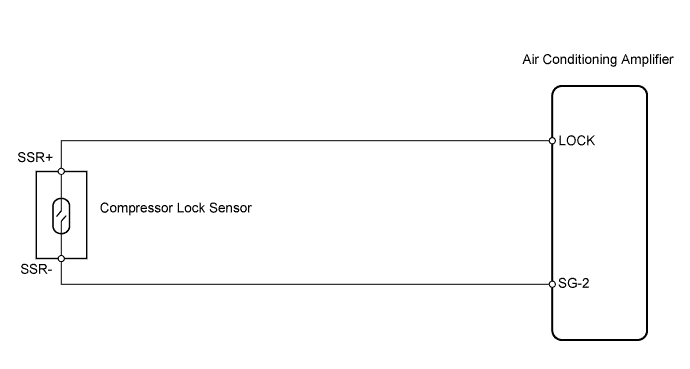
WIRING DIAGRAM
INSPECTION PROCEDURE
CHECK AIR CONDITIONING AMPLIFIER (LOCK SIGNAL)
INSPECT COMPRESSOR LOCK SENSOR
CHECK WIRE HARNESS (COMPRESSOR LOCK SENSOR - AIR CONDITIONING AMPLIFIER)
DTC B1422/22 Compressor Lock Sensor Circuit |
DESCRIPTION
This sensor sends 1 pulse per engine revolution to the air conditioning amplifier. If the ratio of the compressor speed divided by the engine speed is smaller than a predetermined value, the air conditioning amplifier turns the compressor off, and the indicator blinks at approximately 1 second intervals.DTC No.
| DTC Detection Condition
| Trouble Area
|
B1422/22
| Open or short in compressor lock sensor circuit
All conditions below are detected for 3 seconds or more:
1. Engine speed: 450 rpm or more
2. Ratio between engine and compressor speed deviates 20% or more in comparison to normal operation
| - Compressor and magnetic clutch
- Compressor and magnetic clutch drive belt
- Compressor lock sensor
- Harness and connector between compressor lock sensor and air conditioning amplifier
- Air conditioning amplifier
|
WIRING DIAGRAM
INSPECTION PROCEDURE
| 1.CHECK AIR CONDITIONING AMPLIFIER (LOCK SIGNAL) |
Remove the air conditioning amplifier with its connectors still connected.
Check the waveform of the amplifier connector.
- OK:
- Waveform is as shown in the illustration.
Item
| Content
|
Tester Connection
| LOCK (E42-3) - SG-2 (E42-10)
|
Tool Setting
| 500 mV/DIV., 20 msec./DIV.
|
Condition
| Ignition switch on (IG)
A/C switch ON
Magnetic clutch ON
|
- Result:
Result
| Proceed to
|
NG
| A
|
OK (Checking from the PROBLEM SYMPTOMS TABLE)
| B
|
OK (Checking from the DTC)
| C
|
| | PROCEED TO NEXT CIRCUIT INSPECTION SHOWN IN PROBLEM SYMPTOMS TABLE |
|
|
| | REPLACE AIR CONDITIONING AMPLIFIER |
|
|
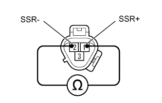
| 2.INSPECT COMPRESSOR LOCK SENSOR |
Disconnect the B82 compressor lock sensor connector.
Measure the resistance of the sensor.
- Standard resistance:
Tester Connection
| Condition
| Specified Condition
|
1 (SSR+) - 2 (SSR-)
| 20°C (68°F)
| 65 to 125 Ω
|
| | REPLACE COMPRESSOR LOCK SENSOR |
|
|
| 3.CHECK WIRE HARNESS (COMPRESSOR LOCK SENSOR - AIR CONDITIONING AMPLIFIER) |
Disconnect the B82 compressor lock sensor connector.
Disconnect the E42 amplifier connector.
Measure the resistance of the wire harness side connectors.
- Standard resistance:
Tester Connection
| Specified Condition
|
B82-1 (SSR+) - E42-3 (LOCK)
| Below 1 Ω
|
B82-2 (SSR-) - E42-10 (SG-2)
| Below 1 Ω
|
B82-1 (SSR+) - E42-10 (SG-2)
| 10 kΩ or higher
|
E42-3 (LOCK) - Body ground
| 10 kΩ or higher
|
| | REPAIR OR REPLACE HARNESS OR CONNECTOR |
|
|
| OK |
|
|
|
| REPLACE AIR CONDITIONING AMPLIFIER |
|