INSTALL IGNITION SWITCH ASSEMBLY (w/o Entry and Start System)
INSTALL UNLOCK WARNING SWITCH ASSEMBLY (w/o Entry and Start System)
INSTALL IGNITION SWITCH LOCK CYLINDER ASSEMBLY (w/o Entry and Start System)
INSPECT STEERING LOCK OPERATION (w/o Entry and Start System)
INSTALL STEERING COLUMN UPPER W/ SWITCH BRACKET ASSEMBLY (w/o Entry and Start System)
INSTALL TRANSPONDER KEY AMPLIFIER (w/o Entry and Start System)
INSTALL STEERING LOCK ACTUATOR ASSEMBLY (w/ Entry and Start System)
Steering Column Assembly (For Rhd) -- Reassembly |
| 1. INSTALL POWER STEERING MOTOR ASSEMBLY |
- NOTICE:
- Do not drop the power steering motor assembly, strike it with tools or subject it to impacts.
- If the power steering motor assembly is subjected to an impact, replace it with a new one.
- Do not pull the wire harness of the power steering motor assembly.
- Do not allow any moisture to come into contact with the power steering motor assembly.
- Do not loosen any bolts not mentioned in the procedure.
Install a new O-ring to the power steering motor assembly.
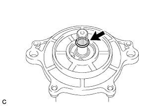 |
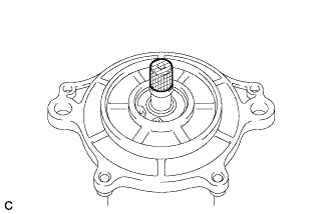
Apply grease to the serrated part of the power steering motor assembly.
- NOTICE:
- First wipe off the existing grease from the serrated part, and then apply the dedicated grease supplied with a new power steering motor assembly or electric power steering column sub-assembly.
 |
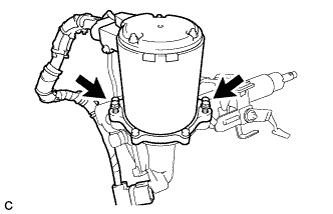
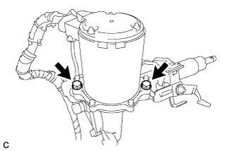
Temporarily install the power steering motor assembly to the electric power steering column sub-assembly with the 2 bolts.
- NOTICE:
- When temporarily installing the 2 bolts to the power steering motor assembly, do not tighten them all the way down.
 |
Install the 2 service nuts to the steering main shaft.
- Recommended service nut:
- Thread diameter:
- 12.0 mm (0.472 in.)
- Thread pitch:
- 1.25 mm (0.0492 in.)
 |
Rotate the 2 installed service nuts simultaneously to lock them: rotate the one installed first counter clockwise and rotate the one installed second clockwise.
- NOTICE:
- Do not apply excess torque to the service nuts by using a tool such as an impact wrench.
- HINT:
- These nuts are installed to turn the steering main shaft. They should be removed after inspecting the steering main shaft rotating torque.
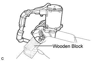
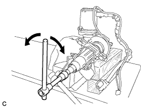
Secure the steering column assembly in a vice using aluminum plates or a piece of cloth as shown in the illustration.
- NOTICE:
- Do not overtighten the vice, as the steering column assembly may become deformed.
- Secure the power steering motor assembly so that it is directly upright.
- Support the steering column assembly with a wooden block or similar item to ensure that it does not fall.
 |
Turn the steering main shaft once 180 degrees to the left and then 180 degrees to the right at a speed of 60 rpm, and repeat 2 to 3 times to adjust the axis of the power steering motor assembly.
 |
Remove the steering column assembly from the vice.
Tighten the 2 bolts.
- Torque:
- 19 N*m{189 kgf*cm, 14 ft.*lbf}
- NOTICE:
- Make sure not to move the power steering motor assembly after adjusting the axis.
 |
Secure the steering column assembly in a vice using aluminum plates or a piece of cloth as shown in the illustration.
- NOTICE:
- Do not overtighten the vice, as the steering column assembly may become deformed.
- Support the steering column assembly with a wooden block or similar item to ensure that it does not fall.
|
Measure the turning torque of the steering main shaft.
- Torque:
- Turning torque:
- 1.20 to 1.85 N*m{13 to 18 kgf*cm, 11 to 16 in.*lbf}
- NOTICE:
- Ensure that there is no abnormal resistance during rotation.
 |
Remove the 2 service nuts from the steering main shaft.
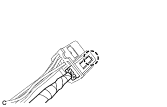
Engage the claw to install the torque sensor harness connector.
 |
Apply tape to the wire harness as shown in the illustration.
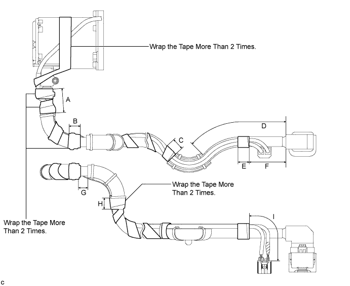
A 40 mm (1.57 in.) B 30 mm (1.18 in.) C 30 mm (1.18 in.) D 145 to 155 mm (5.71 to 6.10 in.) E 30 mm (1.18 in.) F 55 to 65 mm (2.17 to 2.56 in.) G 10 to 20 mm (0.394 to 0.787 in.) H 30 mm (1.18 in.) I 95 to 105 mm (3.74 to 4.13 in.) - NOTICE:
- As heat from the power steering motor assembly may generate smoke, use heat resistant tape (resistant to 100°C (212°F) or more).
| 2. INSTALL IGNITION SWITCH ASSEMBLY (w/o Entry and Start System) |
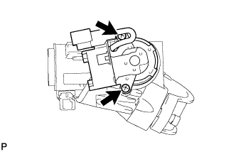 |
Install the ignition switch to the steering column bracket upper with the 2 screws.
| 3. INSTALL KEY INTERLOCK SOLENOID (w/o Entry and Start System) |
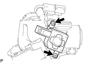 |
for Automatic Transaxle:
Install the key interlock solenoid to the steering column bracket assembly upper with the 2 screws.
| 4. INSTALL UNLOCK WARNING SWITCH ASSEMBLY (w/o Entry and Start System) |
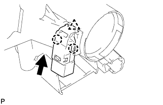 |
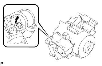
Attach the clip and 2 claws to install the unlock warning switch to the steering column bracket upper.
- HINT:
- Slide the unlock warning switch in the direction shown by the arrow in the illustration to install it.
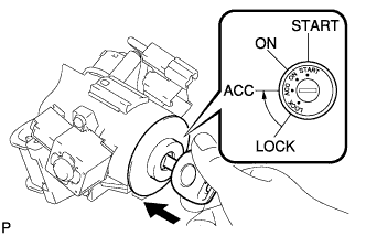
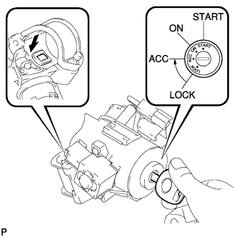
| 5. INSTALL IGNITION SWITCH LOCK CYLINDER ASSEMBLY (w/o Entry and Start System) |
Insert the key and turn it to the ACC position.
Install the ignition switch lock cylinder to the steering column bracket upper.
 |
Make sure that the ignition switch lock cylinder is securely fixed to the steering column upper with switch bracket.
| 6. INSPECT STEERING LOCK OPERATION (w/o Entry and Start System) |
Remove the key and check that the steering lock function is activated.
 |
Insert the key, turn the ignition switch on (ACC) and check that the steering lock function is deactivated.
 |
| 7. INSTALL STEERING COLUMN UPPER W/ SWITCH BRACKET ASSEMBLY (w/o Entry and Start System) |
Fix the steering column in a vise between aluminum plates.
- NOTICE:
- Do not overtighten the vise.
Install the steering column upper with switch bracket with a new steering lock set bolt, and then tighten the bolt until is head comes off.
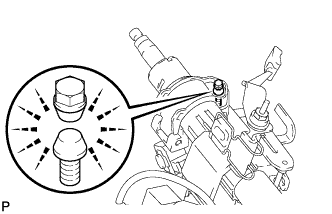 |
| 8. INSTALL TRANSPONDER KEY AMPLIFIER (w/o Entry and Start System) |
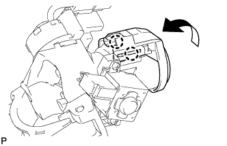 |
Attach the 2 claws and install the transponder key amplifier to the steering column upper with the switch bracket.
| 9. INSTALL STEERING LOCK ACTUATOR ASSEMBLY (w/ Entry and Start System) |
Fix the steering column in a vise between aluminum plates.
- NOTICE:
- Do not overtighten the vise.
Install the steering lock actuator with a steering lock set bolt, and then tighten the bolts until their head comes off.
|