Rear Axle Hub And Bearing -- Removal |
- HINT:
- Use the same procedures for the RH side and LH side.
- The procedures listed below are for the LH side.
| 1. REMOVE REAR WHEEL |
| 2. DISCONNECT CABLE FROM NEGATIVE BATTERY TERMINAL |
- CAUTION:
- Wait at least 90 seconds after disconnecting the cable from the negative (-) battery terminal to prevent airbag and seat belt pretensioner activation.
| 3. REMOVE REAR AXLE SHAFT LH NUT (for 4WD) |
Using SST and hammer, unstake the staked part of the nut.
- SST
- 09930-00010
- NOTICE:
- Loosen the staked part of the nut completely, otherwise the screw of the drive shaft may be damaged.
 |
While applying the brake, remove the lock axle hub nut.
| 4. REMOVE REAR DISC BRAKE CYLINDER ASSEMBLY LH |
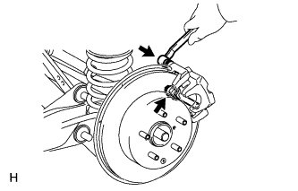 |
Remove the 2 bolts and cylinder.
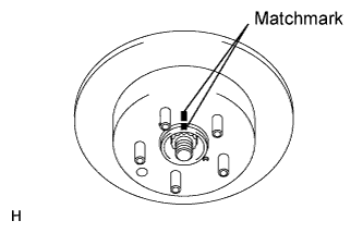
| 5. REMOVE REAR DISC |
Put matchmarks on the disc and axle hub.
 |
Release the parking brake.
Turn the shoe adjuster until the disc turns freely, and then remove the disc.
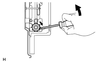 |
Install the shoe adjusting hole plug to the rear disc.
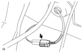
| 6. REMOVE SKID CONTROL SENSOR WIRE (for 2WD) |
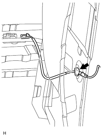
Disconnect the skid control sensor wire connector.
 |
Disconnect the grommet of the skid control sensor wire from the hole of the wheel house.
 |
Remove the bolt (labeled A) and sensor clamp (labeled B) from the side member.
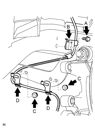 |
Remove the 2 nuts (labeled C) and 2 sensor clamps (labeled D) from the upper arm.
Remove the bolt (labeled E) and sensor clamp (labeled F) from the carrier.
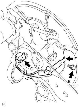 |
Disconnect the skid control sensor wire connector (labeled G) from the skid control sensor.
| 7. REMOVE REAR SPEED SENSOR LH (for 4WD) |
Disconnect the speed sensor connector.
|
Disconnect the grommet of the speed sensor wire from the hole of the wheel house.
|
Remove the bolt (labeled A) and sensor clamp (labeled B) from the side member.
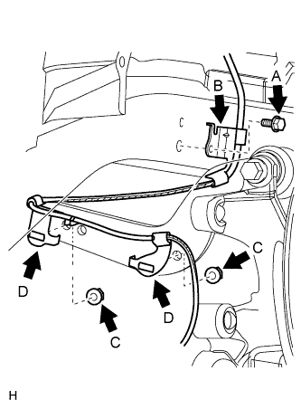 |
Remove the 2 nuts (labeled C) and sensor clamps (labeled D) from the upper arm.
Remove the nut (labeled E) and sensor clamp (labeled F) from the trailing arm.
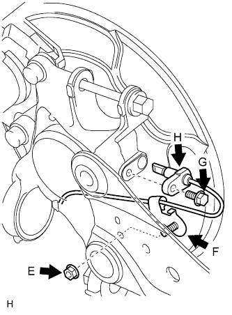 |
Remove the bolt (labeled G) and sensor body (labeled H) from the carrier.
- NOTICE:
- Keep the sensor tip and sensor installation hole free from foreign matter.
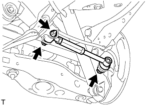
| 8. DISCONNECT REAR SUSPENSION NO. 1 ARM ASSEMBLY LH |
Support the No. 2 suspension arm LH.
 |
Remove the bolt and 2 nuts from the suspension member and axle carrier.
- HINT:
- While fixing the nut in place, loosen and remove the bolt from the suspension member side.
 |
Using SST, disconnect the suspension arm from the axle carrier.
- SST
- 09610-20012
- NOTICE:
- Do not damage the dust cover.
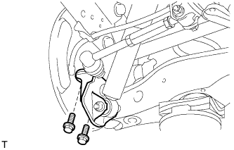
| 9. DISCONNECT REAR SHOCK ABSORBER ASSEMBLY LH |
Remove the 2 bolts and disconnect the shock absorber with bracket from the axle carrier.
 |
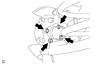
| 10. REMOVE REAR AXLE HUB AND BEARING ASSEMBLY LH |
for 2WD:
Remove the 4 bolts, and axle hub and bearing from the axle carrier.
- NOTICE:
- Do not place the hub and bearing's magnet rotor side so that it is facing downward, and do not allow the magnet rotor side to become damaged or contact foreign matter.
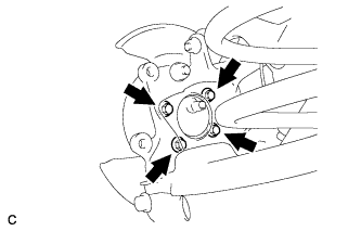 |
for 4WD:
Put matchmarks on the drive shaft and the axle hub and bearing.
Remove the 4 blots, and axle hub and bearing from the axle carrier.
- NOTICE:
- Do not place the hub and bearing's magnet rotor side so that it is facing downward, and do not allow the magnet rotor side to become damaged or contact foreign matter.
 |