Front Axle Hub -- Removal |
- HINT:
- Use the same procedures for the RH side and LH side.
- The procedures listed below are the LH side.
| 1. REMOVE FRONT WHEEL |
| 2. DISCONNECT CABLE FROM NEGATIVE BATTERY TERMINAL |
- CAUTION:
- Wait at least 90 seconds after disconnecting the cable from the negative (-) battery terminal to prevent airbag and seat belt pretensioner activation.
| 3. REMOVE FRONT AXLE SHAFT NUT LH |
Using SST and a hammer, unstake the staked part of the nut.
- SST
- 09930-00010
- NOTICE:
- Loosen the staked part of the nut completely, otherwise the screw of the drive shaft may be damaged.
 |
While applying the brakes, remove the lock axle hub nut.
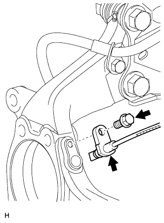
| 4. REMOVE FRONT SPEED SENSOR LH |
Disconnect the sensor connector.
 |
Remove the sensor clip (labeled A), bolt (labeled B) and sensor clamp (labeled C).
 |
Remove the sensor clip (labeled D), bolt (labeled E) and sensor clamp (labeled F).

Remove the bolt and sensor from the knuckle.
- NOTICE:
- Keep the sensor tip and sensor installation hole free from foreign matter.
 |
| 5. REMOVE FRONT DISC BRAKE CYLINDER ASSEMBLY LH |
 |
Remove the 2 bolts and cylinder.
| 6. REMOVE FRONT DISC |
Put matchmarks on the disc and axle hub.
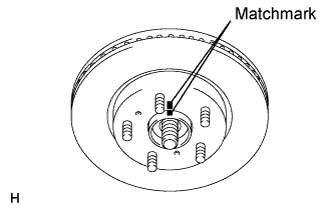 |
Remove the disc.
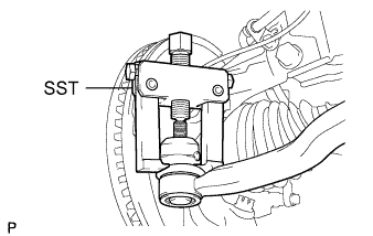
| 7. DISCONNECT TIE ROD END SUB-ASSEMBLY LH |
Remove the cotter pin and castle nut.
Using SST, disconnect the tie rod end from the steering knuckle.
- SST
- 09628-62011
- NOTICE:
- Do not damage the tie rod end dust cover.
 |
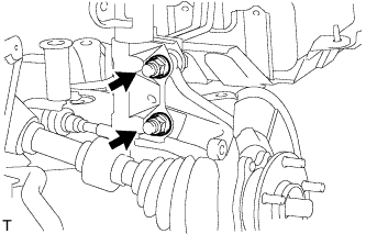
| 8. DISCONNECT FRONT SUSPENSION NO. 1 LOWER ARM SUB-ASSEMBLY LH |
Remove the bolt and 2 nuts.
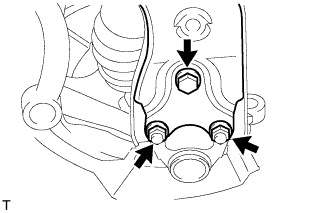 |
Disconnect the lower arm from the ball joint.
| 9. REMOVE STEERING KNUCKLE WITH AXLE HUB |
Remove the 2 bolts and 2 nuts, and disconnect the shock absorber from the steering knuckle.
- HINT:
- While fixing the nuts in place, loosen and remove the bolts.
 |
Put matchmarks on the drive shaft and the axle hub.
 |
Using a plastic-faced hammer, remove the steering knuckle with axle hub.
- NOTICE:
- Be careful not to damage the boot and speed sensor rotor. Do not excessively push out the drive shaft from the axle assembly.
| 10. REMOVE FRONT LOWER BALL JOINT ASSEMBLY LH |
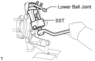 |
Remove the clip and nut.
Using SST, remove the front lower ball joint assembly.
- SST
- 09628-62011
| 11. REMOVE FRONT AXLE HUB SUB-ASSEMBLY LH |
Remove the 4 bolts and axle hub from the steering knuckle.
- NOTICE:
- Do not place the hub and bearing's magnet rotor side so that it is facing downward, and do not allow the magnet rotor side to become damaged or contact foreign matter.
 |
Remove the dust cover from the steering knuckle.