Rear Drive Shaft Assembly -- Removal |
- HINT:
- Use the same procedures for the RH side and LH side.
- The procedures listed below are for the LH side.
| 1. DISCONNECT CABLE FROM NEGATIVE BATTERY TERMINAL |
- CAUTION:
- Wait at least 90 seconds after disconnecting the cable from the negative (-) battery terminal to prevent airbag and seat belt pretensioner activation.
| 2. DRAIN DIFFERENTIAL OIL |
Using a 10 mm socket hexagon wrench, remove the rear differential drain plug and gasket, and drain the oil.
 |
Install a new gasket to the rear differential drain plug.
Using a 10 mm socket hexagon wrench, install the rear differential drain plug and gasket.
| 3. REMOVE REAR WHEEL |
| 4. REMOVE TAILPIPE ASSEMBLY |
for 1AZ-FE:
(RAV4_ACA30 RM000001XBK002X_01_0001.html)
for 2AZ-FE:
(RAV4_ACA30 RM000001XBN01AX_01_0003.html)
for 3ZR-FAE:
(RAV4_ACA30 RM000001XBN01BX_01_0003.html)
for 2GR-FE:
(RAV4_ACA30 RM00000252S007X_01_0004.html)
| 5. REMOVE NO. 2 EXHAUST PIPE SUB-ASSEMBLY |
for 2GR-FE:
(RAV4_ACA30 RM00000252S007X_01_0005.html)
| 6. REMOVE EXHAUST CENTER PIPE ASSEMBLY |
for 1AZ-FE:
(RAV4_ACA30 RM000001XBK002X_01_0002.html)
for 2AZ-FE:
(RAV4_ACA30 RM000001XBN01AX_01_0004.html)
for 3ZR-FAE:
(RAV4_ACA30 RM000001XBN01BX_01_0004.html)
for 2GR-FE:
(RAV4_ACA30 RM00000252S007X_01_0009.html)
| 7. REMOVE FRONT EXHAUST PIPE ASSEMBLY |
for 1AZ-FE:
(RAV4_ACA30 RM000001XBK002X_01_0003.html)
for 2AZ-FE:
(RAV4_ACA30 RM000001XBN01AX_01_0005.html)
for 3ZR-FAE:
(RAV4_ACA30 RM000001XBN01BX_01_0005.html)
for 2GR-FE:
(RAV4_ACA30 RM00000252S007X_01_0007.html)
| 8. REMOVE PROPELLER WITH CENTER BEARING SHAFT ASSEMBLY |
Remove the 2 bolts and 2 adjusting washers, and disconnect the propeller with center bearing shaft.
- NOTICE:
- During the removal, do not exert excessive force on the universal joint.
- When removing, transporting or storing the propeller with center bearing shaft assembly, do not allow the No. 2 joint angle to exceed 20°.
 |
Place matchmarks on the differential carrier and propeller shaft.
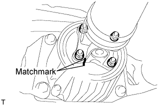 |
Remove the 4 nuts and 4 washers, and disconnect the propeller shaft and differential carrier.
Place matchmarks on the transfer and propeller shaft.
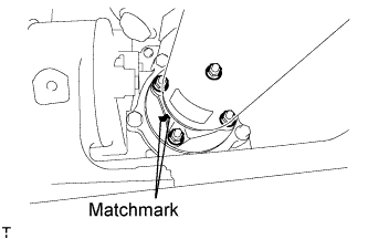 |
Remove the 4 nuts and 4 washers, and disconnect the propeller shaft from the transfer.
| 9. REMOVE REAR AXLE SHAFT NUT |
Using SST and hammer, unstake the staked part of the nut.
- SST
- 09930-00010
- NOTICE:
- Loosen the staked part of the nut completely, otherwise the screw of the drive shaft may be damaged.
 |
While applying the brake, remove the lock axle hub nut.
| 10. DISCONNECT DIFFERENTIAL CARRIER ASSEMBLY |
 |
Support the rear differential carrier with a transmission jack or equivalent.
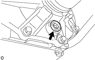
Fix the nuts in place and remove the 2 bolts A and bolt B.
- NOTICE:
- Do not loosen the nuts. Loosen the bolts.
Slowly lower the jack and then tilt the rear differential carrier as shown in the illustration.
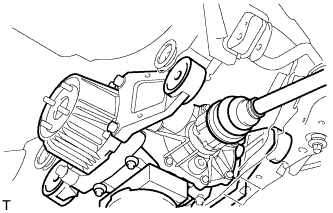 |
With ribs:
Set the tip of the tire lever to the position on the rear drive shaft inboard joint shown in the illustration. Then, using the ribbed part of the rear differential carrier as a fulcrum, disconnect the left and right rear drive shafts.- NOTICE:
- Do not scratch the rear drive shaft dust cover.
 |
Without ribs:
Set the tip of a wheel nut wrench to the position on the rear drive shaft inboard joint shown in the illustration. Then, using a brass bar as a fulcrum, disconnect the left and right rear drive shafts.- NOTICE:
- Do not scratch the rear drive shaft dust cover.
 |
| 11. DISCONNECT REAR SPEED SENSOR LH |
| 12. REMOVE REAR DRIVE SHAFT ASSEMBLY LH |
 |
Put matchmarks on the drive shaft and the axle hub.
- NOTICE:
- Do not punch the marks.
Using a plastic-faced hammer, separate the drive shaft from the axle hub.
- NOTICE:
- Be careful not to damage the boot and speed sensor rotor. Do not excessively push out the drive shaft from the axle.