Transmission Control Cable -- Installation |
| 1. INSTALL TRANSMISSION CONTROL CABLE ASSEMBLY |
- NOTICE:
- Before installing the transmission control cable assembly, check that the park/neutral position switch and shift lever are in neutral.
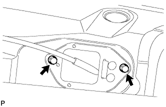
Put the transmission control cable into the cabin and connect the transmission control cable with the 2 bolts.
- Torque:
- 5.0 N*m{51 kgf*cm, 44 in.*lbf}
 |
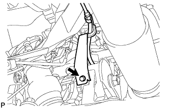
Connect the clamp of the control cable with the bolt.
- Torque:
- 5.0 N*m{51 kgf*cm, 44 in.*lbf}
 |
Connect the transmission control cable to the control cable support.
 |
Connect the transmission control cable to the bracket with a new clip.
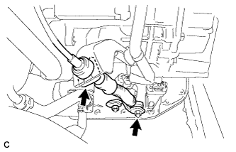 |
Connect the transmission control cable to the control shaft lever with the nut.
- Torque:
- 12 N*m{122 kgf*cm, 9 ft.*lbf}
Turn the nut of the transmission control cable 180° counterclockwise. While holding the nut in place, push in the stopper to lock the nut.
- NOTICE:
- Do not over-rotate the nut as it will come off the internal spring and the transmission control cable will not be reusable.
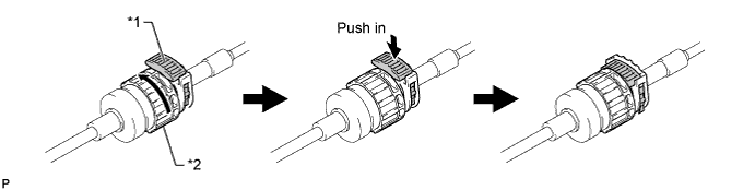
Text in Illustration *1 Stopper *2 Nut - HINT:
- If the stopper cannot be pushed in, slightly turn the nut clockwise and then push in the stopper again.
Install the outer part of the transmission control cable to the shift lever retainer. Check that the stopper returns to the pulled out position.
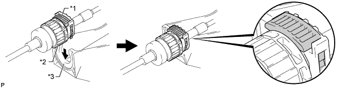
Text in Illustration *1 Stopper *2 Nut *3 Shift Lever Retainer - -
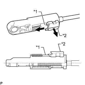
Slide the slider in the direction shown in the illustration and pull out the lock piece.
Text in Illustration *1 Slider *2 Lock Piece
 |
Connect the end of the cable to the shift lever.
- NOTICE:
- Make sure that the lock piece is pulled up.
- Push on the end of the cable all the way to the base of the pin.
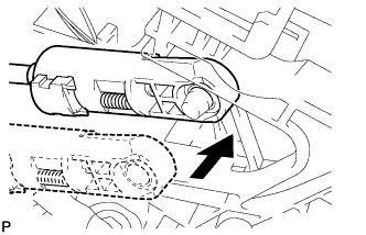 |
Gently pull the cable rod toward the rear of the vehicle by hand to pull the cable taut.
Text in Illustration *1 Cable Rod
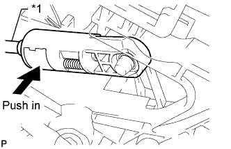 |
Push the lock piece into the adjuster case and lock it.
- NOTICE:
- Make sure that the lock piece is completely locked by the slider.
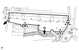
| 2. INSTALL FRONT FLOOR COVER |
Install the floor under cover with the 3 clips, bolt and nut.
- Torque:
- for bolt:
- 12 N*m{122 kgf*cm, 9 ft.*lbf}
- for nut:
- 6.0 N*m{61 kgf*cm, 53 in.*lbf}
 |
| 3. INSTALL AIR CLEANER CASE |
Install the air cleaner case with the 3 bolts.
- Torque:
- 5.0 N*m{51 kgf*cm, 44 in.*lbf}
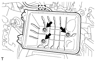 |
Attach the wire harness clamp to the air cleaner case.
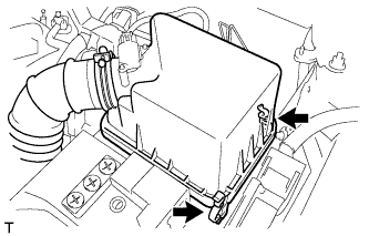
| 4. INSTALL AIR CLEANER CAP AND HOSE |
Insert the hinge part of the air cleaner cap and hose into the air cleaner case, and then fasten the 2 hook clamps.
 |
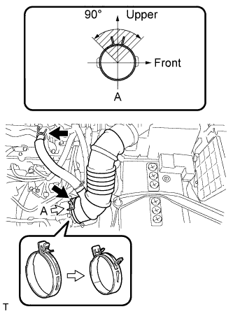
Connect the No. 1 air cleaner hose to the throttle body and push apart the tabs of the No. 1 air cleaner hose clamp.
- HINT:
- The direction of the hose clamp is indicated in the illustration.
 |
Connect the No. 2 ventilation hose to the cylinder head cover.
Attach the clamp.
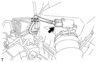 |
Connect the mass air flow meter connector.
| 5. INSTALL BATTERY BRACKET REINFORCEMENT |
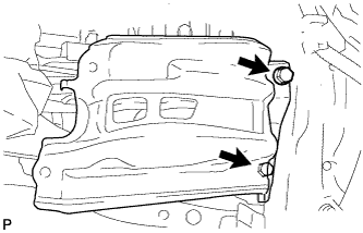
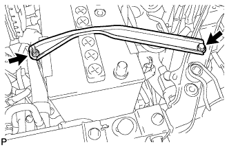
Install the battery bracket reinforcement with the 2 bolts.
- Torque:
- 20 N*m{204 kgf*cm, 15 ft.*lbf}
 |
| 6. INSTALL FRONT BATTERY BRACKET |
Install the front battery bracket with the 3 bolts.
- Torque:
- 20 N*m{204 kgf*cm, 15 ft.*lbf}
 |
Connect the No. 3 engine wire with the bolt.
- Torque:
- 20 N*m{204 kgf*cm, 15 ft.*lbf}
Attach the 3 wire harness clamps.
| 7. INSTALL BATTERY |
Install the battery tray.
Install the battery.
Attach the hook of the battery clamp to the front battery bracket to install the battery clamp.
 |
Partially tighten the nut and temporarily install the bolt.
Adjust the battery clamp position.
Tighten the nut and bolt.
- Torque:
- for bolt:
- 17 N*m{168 kgf*cm, 12 ft.*lbf}
- for nut:
- 4.9 N*m{50 kgf*cm, 43 in.*lbf}
Connect the cable to the positive (+) battery terminal.
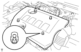
| 8. INSTALL NO. 2 CYLINDER HEAD COVER |
Attach the 4 clips to install the cover.
- NOTICE:
- Be sure to attach the clips securely.
- Do not apply excessive force or do not hit the cover to attach the clips. This may cause the cover to break.
 |
| 9. CONNECT CABLE TO NEGATIVE BATTERY TERMINAL |
| 10. INSPECT SHIFT LEVER POSITION |
When moving the shift lever from P to R with the ignition switch ON and the brake pedal depressed, make sure that the shift lever moves smoothly and correctly into position.
Start the engine and make sure that the vehicle moves forward after moving the shift lever from N to D and moves in reverse after moving the shift lever to R.
If the operation cannot be performed as specified, inspect the park/neutral position switch assembly and check the shift lever assembly installation condition.
| 11. ADJUST SHIFT LEVER POSITION |
Remove the rear console box sub-assembly (RAV4_ACA30 RM000001RHJ00GX.html).
Apply the parking brake and move the shift lever to N.
Slide the slider in the direction shown in the illustration and pull out the lock piece.
Text in Illustration *1 Slider *2 Lock Piece
|
Gently pull the cable rod toward the rear of the vehicle by hand to pull the cable taut.
Text in Illustration *1 Cable Rod
|
Press the lock piece into the adjuster case and lock it.
- NOTICE:
- Make sure that the lock piece is completely locked by the slider.
Inspect the operation of the shift lever (RAV4_ACA30 RM0000023CF01HX.html).
Install the rear console box sub-assembly (RAV4_ACA30 RM000001RHG00HX.html).
| 12. INSTALL REAR CONSOLE BOX SUB-ASSEMBLY |
Install the rear console box (RAV4_ACA30 RM000001RHG00HX.html).