INSTALL OVERDRIVE DIRECT CLUTCH O-RING
INSTALL OVERDRIVE DIRECT CLUTCH DRUM SUB-ASSEMBLY
INSTALL OVERDRIVE DIRECT CLUTCH PISTON
INSTALL OVERDRIVE CLUTCH RETURN SPRING SUB-ASSEMBLY
INSTALL OVERDRIVE DIRECT CLUTCH DISC
INSTALL DIRECT MULTIPLE DISC CLUTCH DISC
INSPECT PACK CLEARANCE OF DIRECT CLUTCH AND OVERDRIVE CLUTCH
INSPECT PACK CLEARANCE OF REVERSE CLUTCH
INSPECT DIRECT CLUTCH ASSEMBLY
Direct Clutch -- Reassembly |
| 1. INSTALL OVERDRIVE DIRECT CLUTCH O-RING |
Coat an O-ring with ATF, and install it to the direct clutch drum.
- NOTICE:
- Make sure that the O-ring is not twisted or pinched when it is installed.
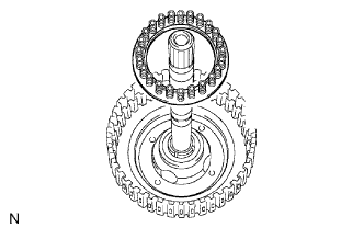
| 2. INSTALL OVERDRIVE DIRECT CLUTCH DRUM SUB-ASSEMBLY |
Coat the direct clutch drum with ATF, and install it to the intermediate shaft.
- NOTICE:
- Be careful not to damage the O-ring.
- Be careful not to damage the lip of the direct clutch drum.
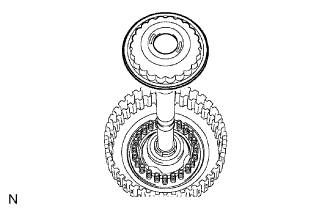
| 3. INSTALL OVERDRIVE DIRECT CLUTCH PISTON |
Coat the overdrive direct clutch piston with ATF, and install it to the direct clutch drum.
| 4. INSTALL OVERDRIVE CLUTCH RETURN SPRING SUB-ASSEMBLY |
Install the overdrive clutch return spring to the direct clutch drum.
- NOTICE:
- After installing the spring sub-assembly, check that all of the springs fit in the piston correctly.
Coat the clutch balancer with ATF.
Install the clutch balancer to the direct clutch drum.
- NOTICE:
- Be careful not to damage the lip of the direct clutch balancer.
- Make sure that the lip of the seal is not pinched or has any other defects.
- Apply sufficient ATF to the sealing lip before installing the clutch balancer.
Place SST on the clutch balancer and compress the overdrive clutch return spring with a press.
- SST
- 09387-00020
Using a snap ring expander, install the snap ring to the direct clutch drum.
Make sure that the end gap of the snap ring is not aligned with the spring retainer claw.
- NOTICE:
- Stop the press when the spring seat is lowered to a position 1 to 2 mm (0.039 to 0.078 in.) from the snap ring groove. This prevents the spring seat from being deformed.
- Do not expand the snap ring excessively.
Set the end gap of the snap ring in the piston as shown in the illustration.
- NOTICE:
- The end gap of the snap ring should not align with any of the stoppers.
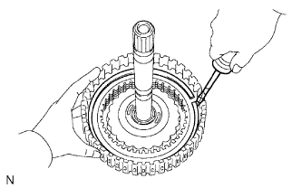
| 5. INSTALL OVERDRIVE DIRECT CLUTCH DISC |
Coat the 4 discs with ATF.
Install the 4 plates, 4 discs and flange to the intermediate shaft.
- NOTICE:
- Make sure that the plates, discs and flange are installed as shown in the illustration.
Using a screwdriver, install the snap ring.
Check that the end gap of the snap ring is not aligned with one of the cutouts.
- NOTICE:
- The snap ring should be fully engaged in the groove of the drum.
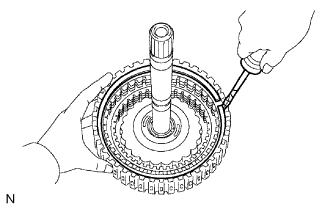
| 6. INSTALL DIRECT MULTIPLE DISC CLUTCH DISC |
Coat the 3 discs with ATF.
Install the cushion plate, 3 plates, 3 discs and flange to the intermediate shaft.
- NOTICE:
- Install the cushion plate with the mark on the white surface facing the plate.
- Make sure that the cushion plate, discs, plates and flange are installed in the correct order.
Using a screwdriver, install the snap ring.
Check that the end gap of the snap ring is not aligned with one of the cutouts.
- NOTICE:
- The snap ring should be fully engaged in the groove of the drum.
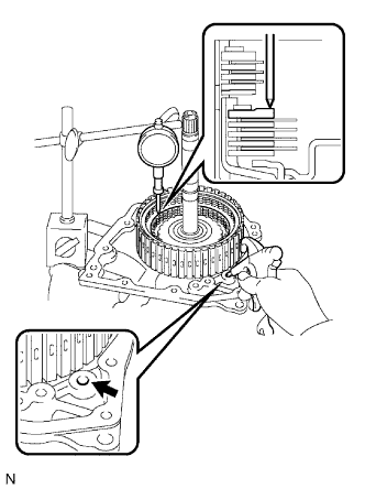
| 7. INSPECT PACK CLEARANCE OF DIRECT CLUTCH AND OVERDRIVE CLUTCH |
Using a dial indicator, measure the direct clutch and overdrive clutch pack clearance while applying and releasing compressed air (392 kPa, 4.0 kgf/cm2, 57 psi).
- Standard pack clearance:
- 0.61 to 0.83 mm (0.0240 to 0.0327 in.)
If the pack clearance is less than the minimum, parts may have been assembled incorrectly, so check and reassemble them again. If the clearance is not as specified, select another flange.
- HINT:
- There are 7 different thicknesses of flanges available.
- Standard flange thickness:
No.
| Thickness
| No.
| Thickness
|
0
| 2.5 mm (0.098 in.)
| 4
| 2.9 mm (0.114 in.)
|
1
| 2.6 mm (0.102 in.)
| 5
| 3.0 mm (0.118 in.)
|
2
| 2.7 mm (0.106 in.)
| 6
| 3.1 mm (0.122 in.)
|
3
| 2.8 mm (0.110 in.)
| -
| -
|
| 8. INSPECT PACK CLEARANCE OF REVERSE CLUTCH |
Install the intermediate shaft onto the transaxle rear cover.
Using a dial indicator, measure the direct clutch pack clearance while applying and releasing compressed air (392 kPa, 4.0 kgf/cm2, 57 psi).
- Standard clearance:
- 0.60 to 0.82 mm (0.0236 to 0.0323 in.)
If the pack clearance is less than the minimum, parts may have been assembled incorrectly, so check and reassemble them again. If the clearance is not as specified, select another flange.
- HINT:
- There are 7 different thicknesses of flanges available.
- Standard flange thickness:
No.
| Thickness
| No.
| Thickness
|
1
| 3.0 mm (0.118 in.)
| 5
| 3.4 mm (0.134 in.)
|
2
| 3.1 mm (0.122 in.)
| 6
| 3.5 mm (0.138 in.)
|
3
| 3.2 mm (0.126 in.)
| 7
| 3.6 mm (0.142 in.)
|
4
| 3.3 mm (0.130 in.)
| -
| -
|
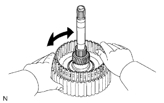
| 9. INSPECT DIRECT CLUTCH ASSEMBLY |
Check that the disc rotates after inserting the rear planetary sun gear.
- NOTICE:
- Do not place the rear planetary sun gear in a vise.