Lexus IS250 IS220d GSE20 ALE20 2AD-FHV COOLING
RADIATOR - INSTALLATION
| 1. INSTALL RADIATOR ASSEMBLY |
Install the 2 radiator support cushions and the 2 lower radiator support cushions to the radiator assembly.
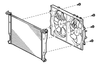
Install the fan assembly to the radiator with the 4 bolts.
- Torque:
- 5.0 N*m{ 51 kgf*cm, 44 in.*lbf}
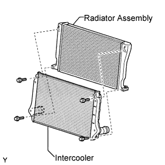
Install the intercooler with the 4 bolts and washer.
- Torque:
- 6.0 N*m{ 62 kgf*cm, 54 in.*lbf}
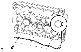
Install the vacuum transmitting pipe to the fan assembly with the 3 bolts.
- Torque:
- 6.0 N*m{ 61 kgf*cm, 53 in.*lbf}
Install the vacuum transmitting pipe to the intercooler and secure it with the clip.
- HINT:
- Make sure that the claws on the clip are positioned as shown in the illustration.
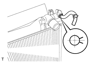
Install the reserve tank hose to the radiator assembly and secure it with the clip.
- HINT:
- Make sure that the claws on the clip are positioned as shown in the illustration.
Install the radiator outlet hose to the radiator assembly with the bolt.
- Torque:
- 6.0 N*m{ 61 kgf*cm, 53 in.*lbf}
Install the No. 3 radiator hose to the radiator assembly and secure it with the clip.
- HINT:
- Make sure that the claws on the clips are positioned as shown in the illustration.
| 2. CONNECT COOLER CONDENSER ASSEMBLY |
Install the radiator assembly to the vehicle together with the intercooler and the cooling fan assembly.
- NOTICE:
- Make sure that the cooler condenser assembly and radiator assembly do not come into contact with each other.
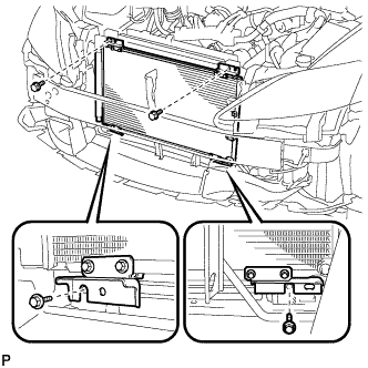
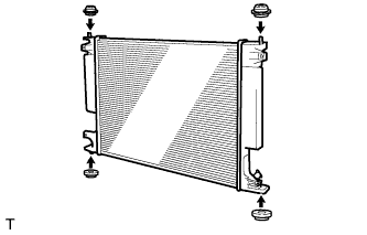
Install the cooler condenser assembly to the radiator assembly with the 4 bolts.
- Torque:
- 5.0 N*m{ 51 kgf*cm, 44 in.*lbf}
| 3. CONNECT NO. 3 AIR HOSE |
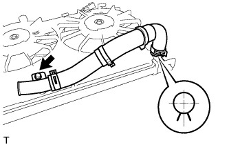
Install the No. 3 air hose to the intercooler and secure it with the clip.
- HINT:
- Make sure that the claws on the clip are positioned as shown in the illustration.
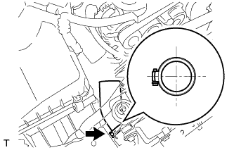
| 4. CONNECT RADIATOR OUTLET HOSE |
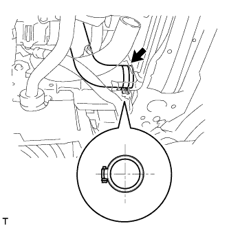
Install the radiator outlet hose to the radiator assembly and secure it with the clip.
- HINT:
- Make sure that the claws on the clip are positioned as shown in the illustration.
| 5. CONNECT VACUUM TRANSMITTING HOSE |
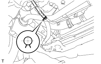
Install the vacuum transmitting hose to the vacuum transmitting pipe and secure it with the clip.
- HINT:
- Make sure that the claws on the clip are positioned as shown in the illustration.
| 6. INSTALL NO. 2 AIR HOSE |
Install the No. 2 air hose to the intercooler and secure it with the clip.
- HINT:
- Make sure that the claws on the clip are positioned as shown in the illustration.
| 7. INSTALL NO. 1 AIR TUBE |
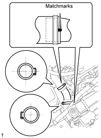
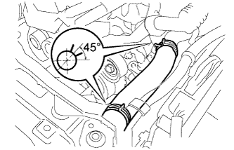
Align the matchmarks, install the No. 1 air tube to the intercooler and secure it with the 2 clips.
- HINT:
- Make sure that the claws on the 2 clips are positioned as shown in the illustration.
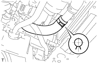
| 8. INSTALL RADIATOR INLET HOSE |
Install the radiator inlet hose to the radiator assembly and secure it with the 2 clips.
- HINT:
- Make sure that the claws on the 2 clips are positioned as shown in the illustration.
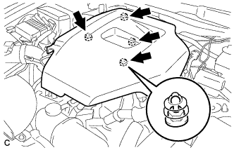
| 9. INSTALL UPPER RADIATOR SUPPORT |
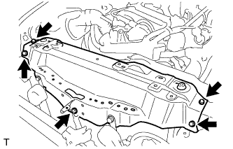
Install the upper radiator support with the 4 bolts.
- Torque:
- 8.0 N*m{ 82 kgf*cm, 71 in.*lbf}
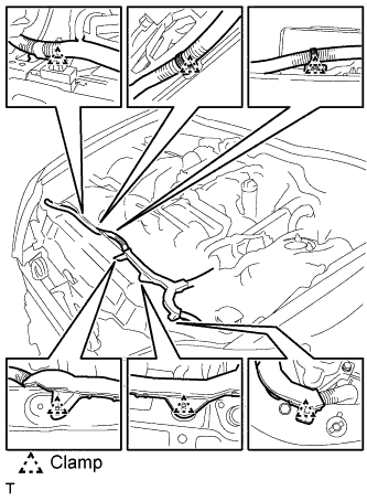
Install the 6 wire harness clamps and the No. 2 engine room wire.
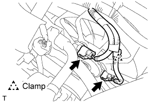
Connect the clamp and the 2 cooling fan motor connectors.
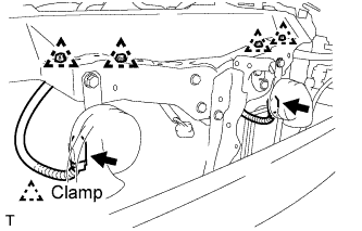
Connect the 4 wire harness clamps and the 2 connectors.
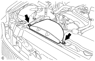
| 10. INSTALL HOOD LOCK ASSEMBLY |
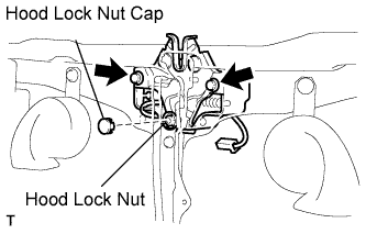
Install the 2 bolts and the hood lock assembly to the upper radiator support.
- Torque:
- 8.0 N*m{ 82 kgf*cm, 71 in.*lbf}
Install the hood lock nut and the hood lock nut cap.
- Torque:
- 8.0 N*m{ 82 kgf*cm, 71 in.*lbf}
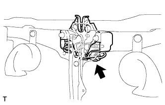
Connect the connector.
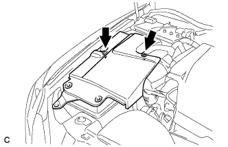
| 11. INSTALL HOOD LOCK CONTROL CABLE COVER |
Connect the clamp, and install the 3 screws and the hood lock control cable cover.
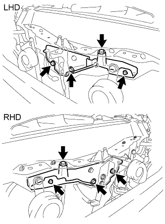
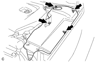
| 12. INSTALL RADIATOR RESERVE TANK |
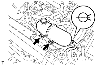
Install the radiator reserve tank to the upper radiator support with the 2 bolts.
- Torque:
- 5.0 N*m{ 51 kgf*cm, 44 in.*lbf}
Install the reserve tank hose to the radiator reserve tank and secure it with the clip.
- HINT:
- Make sure that the claws on the clip are positioned as shown in the illustration.
Install the reserve tank outlet hose to the radiator reserve tank and secure it with the clip.
- HINT:
- Make sure that the claws on the clip are positioned as shown in the illustration.
| 13. INSTALL FRONT BUMPER ENERGY ABSORBER |
| 14. INSTALL FRONT BUMPER ASSEMBLY |
| 15. CONNECT BATTERY NEGATIVE TERMINAL |
- Torque:
- 5.4 N*m{ 55 kgf*cm, 48 in.*lbf}
| 16. ADD ENGINE COOLANT |
Tighten all the plugs.
- Torque:
- for cylinder block drain cock plug:
- 20 N*m{ 204 kgf*cm, 15 ft.*lbf}
Add engine coolant.
- Specified capacity:
- 8.9 liters (9.4 US qts, 7.8 lmp. qts)
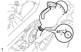
- HINT:
Slowly pour coolant into the radiator reservoir until it reaches the FULL line.
Squeeze the inlet and outlet radiator hoses several times by hand, and then check the level of the coolant.
If the coolant level is low, add coolant.
Install the radiator cap.
Bleed air from the cooling system.
- NOTICE:
- Before starting the engine, turn the A/C switch off.
Warm up the engine until the thermostat opens. While the thermostat is open, allow the coolant to circulate for several minutes.
- HINT:
- The thermostat open timing can be confirmed by squeezing the inlet radiator hose by hand, and sensing vibrations when the engine coolant starts to flow inside the hose.
- NOTICE:
- When squeezing the radiator hose:
Maintain the engine speed at 2,000 to 2,500 rpm.
Squeeze the inlet and outlet radiator hoses several times by hand to bleed air from the system.
- NOTICE:
- When squeezing the radiator hoses:
Stop the engine and wait until the engine coolant cools down to ambient temperature.
- CAUTION:
- Do not remove the radiator cap while the engine and radiator are still hot. Pressurized, hot engine coolant and steam may be released and cause serious burns.
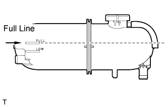
Check the coolant level in the reserve tank.
If the coolant level is low, add coolant to the reserve tank FULL line.
| 17. CHECK FOR ENGINE COOLANT LEAKAGE |
- CAUTION:
- Do not remove the radiator cap while the engine and radiator are still hot. Pressurized, hot engine coolant and steam may be released and cause serious burns.
- NOTICE:
- Before performing each inspection, turn the A/C switch off.
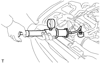
Fill the radiator with coolant and attach a radiator cap tester.
Warm up the engine.
Using a radiator cap tester, increase the pressure inside the radiator to 177 kPa (1.8 kgf/cm, 26 psi), and check that the pressure does not drop.
If the pressure drops, check the hoses, radiator and water pump for leaks. If no external leaks are found, check the heater core, cylinder block and cylinder head.
| 18. INSTALL ENGINE UNDER COVER |
| 19. INSTALL NO. 1 ENGINE COVER |
Install the No. 1 engine cover.
| 20. INSTALL NO. 1 INLET AIR CLEANER |
Install the inlet air cleaner with the bolt and clip.
- Torque:
- 5.0 N*m{ 51 kgf*cm, 44 in.*lbf}
| 21. INSTALL ENGINE ROOM SIDE COVER LH |
Install the side cover with the 4 clips.
| 22. INSTALL ENGINE ROOM SIDE COVER RH |
Install the side cover with the 2 clips.
| 23. INSTALL COOL AIR INTAKE DUCT SEAL |

Install the intake duct seal with the 11 clips.
| 24. VEHICLE PREPARATION FOR FOG LIGHT AIM |
Prepare the vehicle:
| 25. PREPARATION FOR FOG LIGHT AIMING |
Prepare the vehicle according to the following conditions:
- NOTICE:
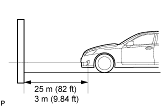
- A distance of 25 m (82 ft) between the vehicle (fog light bulb center) and the wall is necessary for proper aim adjustment. If unavailable, secure a distance of exactly 3 m (9.84 ft) for check and adjustment. (The target zone will change with the distance, so follow the instructions in the illustration.)
Prepare a piece of thick white paper (approximately 2 m (6.6 ft) (height) x 4 m (13.1 ft) (width)) to use as a screen.
Draw a vertical line down the center of screen (V line).
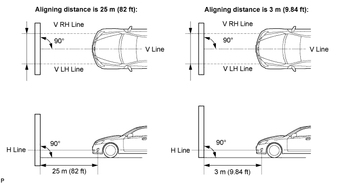
Set the screen as shown in the illustration.
- HINT:
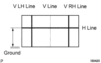
Draw base lines (H line, V LH, V RH lines) on the screen as shown in the illustration.
- HINT:
- Mark the fog light bulb center marks on the screen. If the center mark cannot be observed on the fog light, use the center of the fog light bulb or the manufacturer's name marked on the fog light as the center mark.
H Line (Fog light height):
Draw a horizontal line across the screen so that it passes through the center marks. The H line should be at the same height as the fog light bulb center marks of the low-beam fog lights.
V LH Line, V RH Line (Center mark position of left-hand (LH) and right-hand (RH) fog lights):
Draw two vertical lines so that they intersect the H line at each center mark.
| 26. FOG LIGHT AIMING INSPECTION |
Cover the fog light or disconnect the connector of the fog light on the opposite side to prevent light from the fog light not being inspected from affecting fog light aiming inspection.
Start the engine.
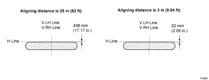
Turn on the fog light and make sure that the cutoff line falls within the specified area, as shown in the illustration.
| 27. FOG LIGHT AIMING ADJUSTMENT |
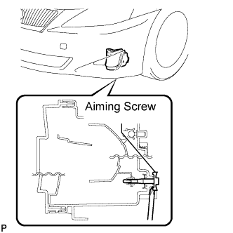
Adjust the fog light aim into the specified range by turning the aiming screw with a screwdriver.
- NOTICE:
- The final turn of the aiming screw should be made in the clockwise direction. If the screw is tightened excessively, loosen it and then retighten it, so that the final turn of the screw is in the clockwise direction.
| 28. PERFORM INITIALIZATION |
Perform initialization procedure .
- HINT:
- Some vehicle systems require initialization after reconnecting the negative battery terminal.